Battery Energy Storage System Diagram (BESS Block Diagram)
This battery energy storage system diagram maps the whole plant as a stack of layers, from the grid connection down to the cell — point of interconnection, GSU transformer, medium-voltage collection, energy station, PCS and MV skid, container, rack, module, and cell, each layer named and shown with its own interactive engineering visual.
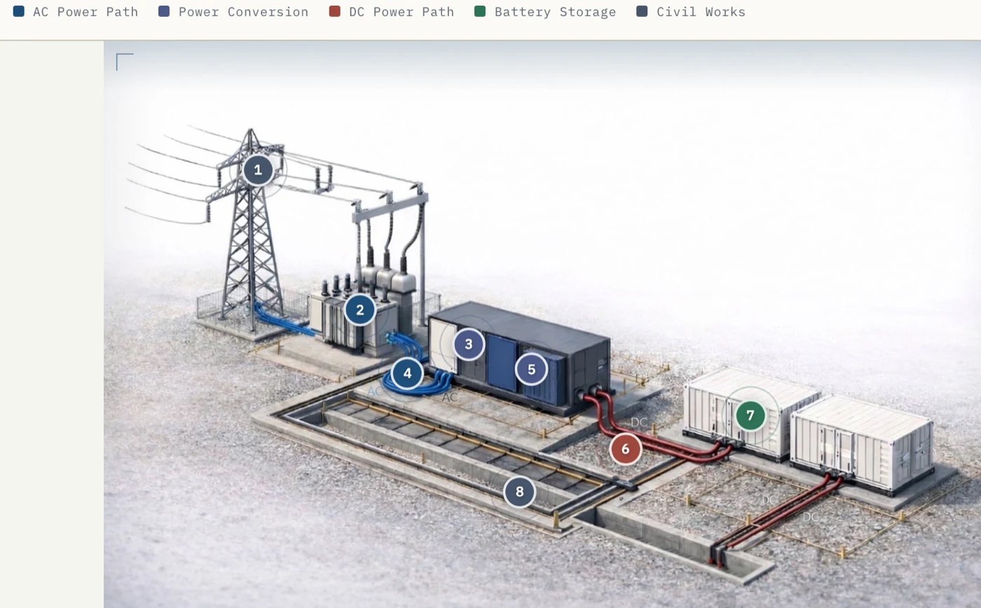
1 · The whole site, at a glance
A grid-scale BESS is a repeated pattern of energy stations feeding a shared connection to the grid. Power flows from the point of interconnection (POI) through a grid step-up (GSU) transformer, down a medium-voltage (MV) collection network, into each energy station, and finally into the battery containers. The interactive site map traces every one of those components and the path between them.
2 · The energy station — where AC meets DC
Each energy station is where alternating current from the grid is converted to the direct current the batteries store, and back again. The medium-voltage AC is stepped down to the power conversion system (PCS), which rectifies it to DC for the battery blocks; on discharge the PCS runs in reverse. This is the AC/DC boundary of the whole plant — everything upstream is AC, everything in the container is DC.
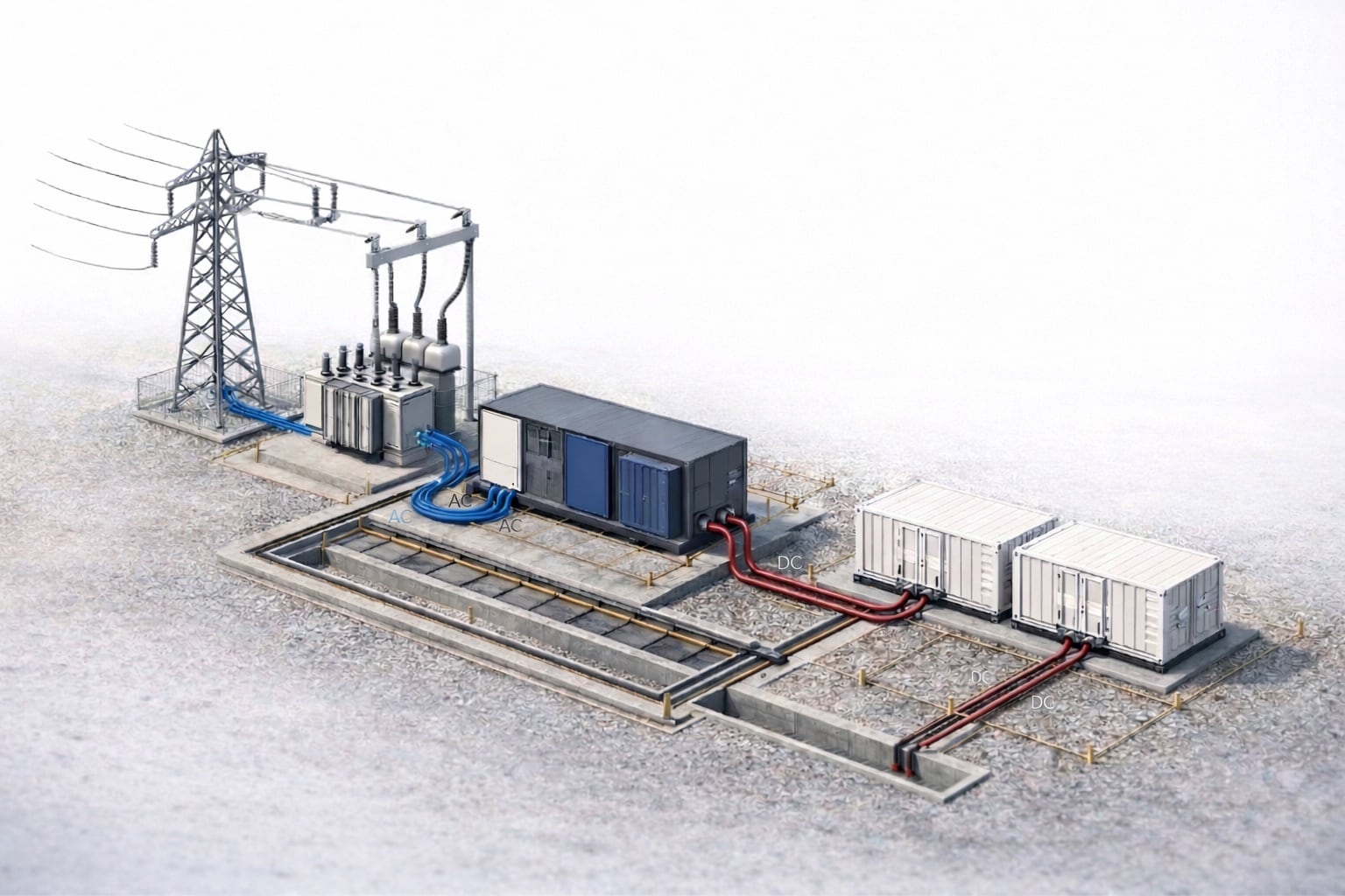
3 · The MV skid — PCS and transformer
The MV skid is a factory-assembled frame carrying the power conversion system (the inverter), its step-up transformer, switchgear, and auxiliary power, wired as one transportable unit. The PCS sets the plant’s AC power rating in MW; the transformer lifts its low-voltage output to the medium-voltage collection level (typically 11–33 kV). It is the electrical heart of the station.
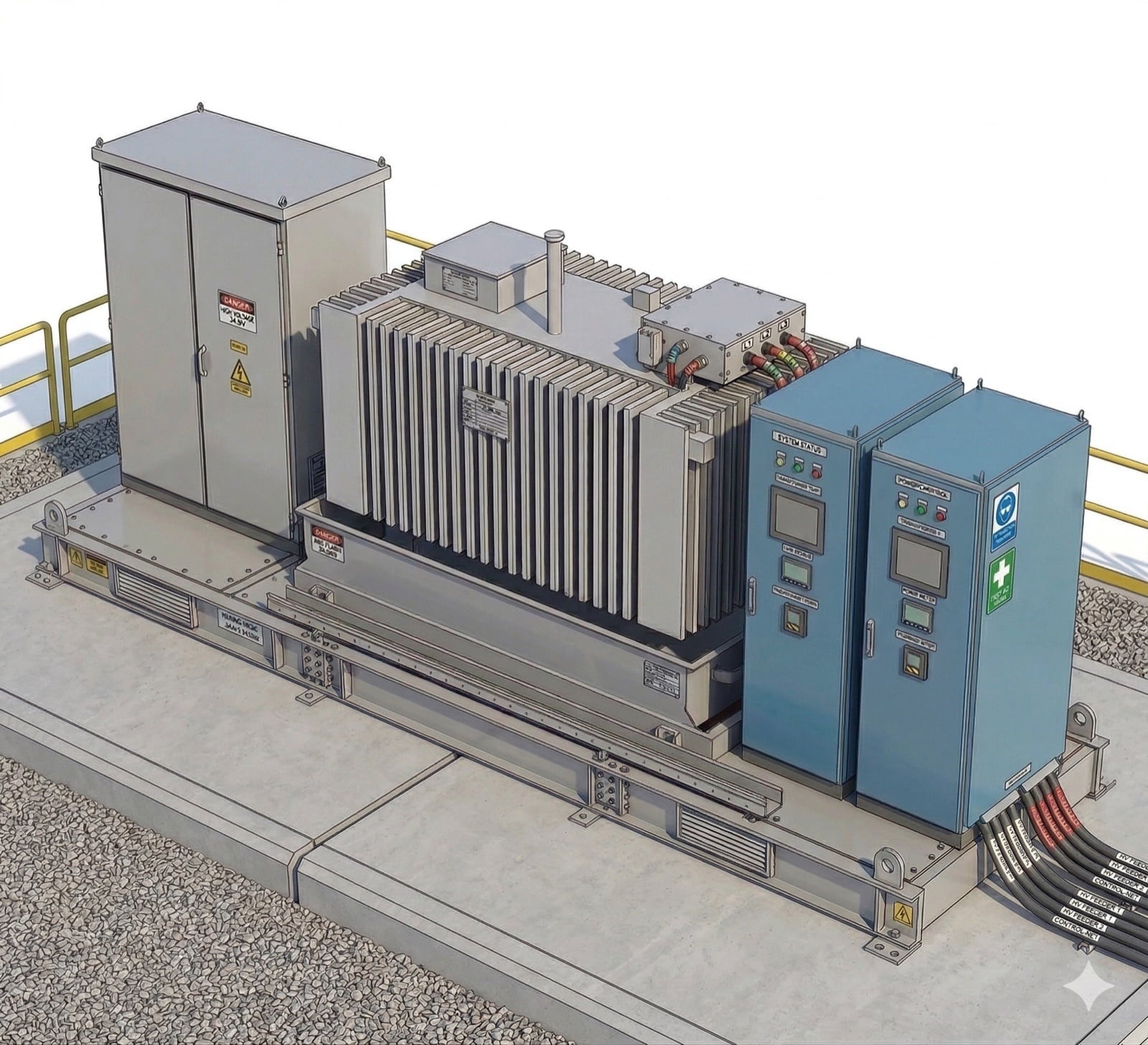
4 · The container — where the energy lives
The battery container (or enclosure) holds the energy the plant is rated for, in MWh. Inside, cells are grouped into modules, modules into racks, and racks fill the container, alongside the thermal (HVAC) system that holds cells in their safe temperature band and the fire-detection and deflagration-venting provisions required by NFPA 855. The ratio of container energy (MWh) to station power (MW) is what sets the system’s duration in hours.
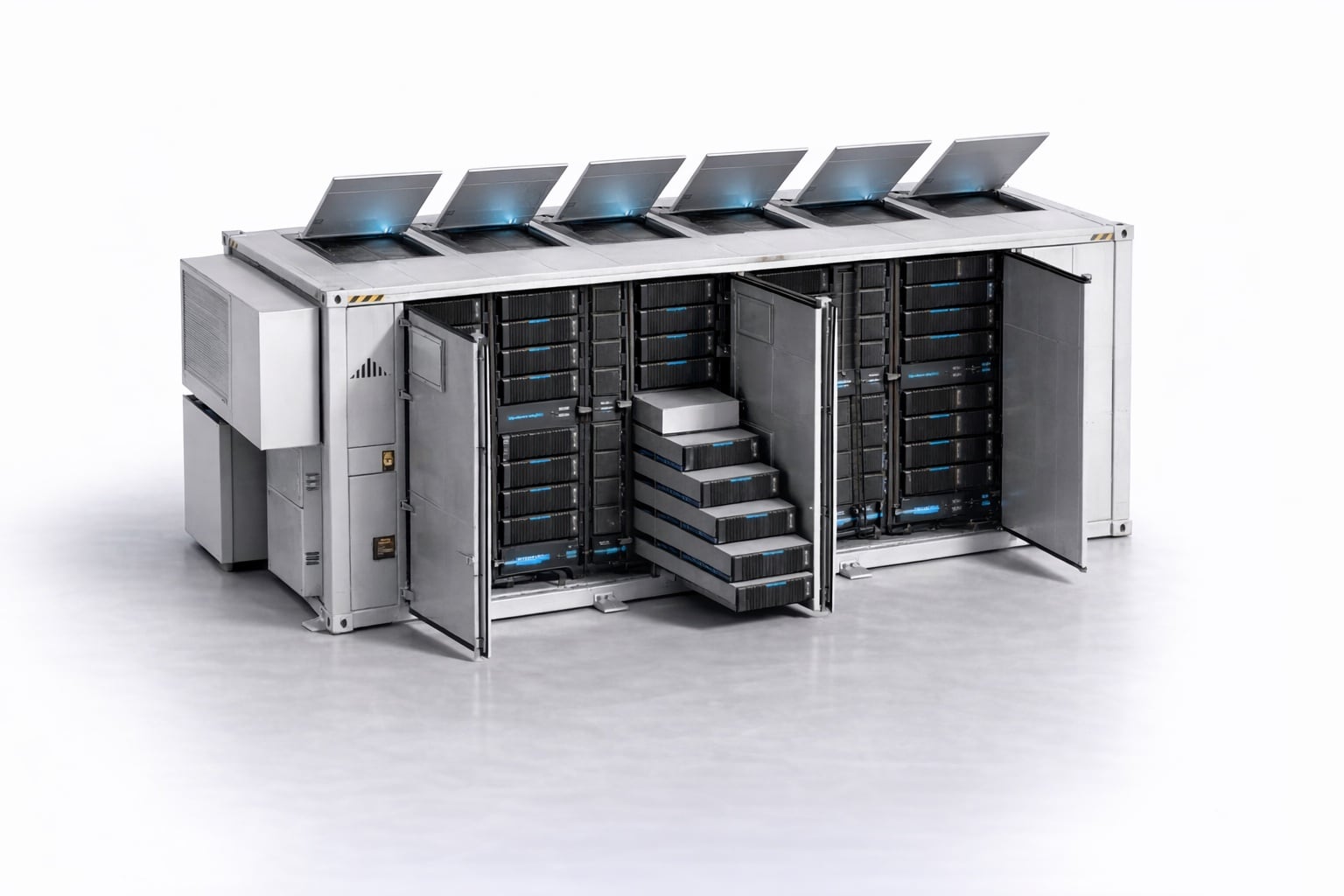
5 · The BMS — three layers of protection
The battery management system watches every cell and keeps the pack inside its safe voltage, current, and temperature limits. It is built in three tiers: a module-level unit (BMU) senses individual cells, a rack-level controller (BCU) manages a string, and a container-level unit (BAU) coordinates the whole enclosure and talks to the plant controller. The BMS — not the PCS or EMS — owns cell safety.
Hover, focus, or tap a layer in the hierarchy. The cutaway and photo overlay light up where that BMS layer is installed.
One container = 1 BAU + 12 BCUs + 48 BMUs keeping watch over 4,992 cells.
Counts: 12 BESS racks x 4 modules x 104 cells. One physical rack = two BESS racks: four modules above the BCUs and four below.
6 · Down to the cell
At the bottom of the diagram is the electrochemical cell. On charge, lithium ions move through the electrolyte from cathode to anode while electrons take the external circuit; on discharge the flow reverses and the cell delivers power. Thousands of these cells, in series and parallel, add up to the container’s energy — and their chemistry (LFP, NMC, or emerging sodium-ion) sets the whole system’s safety, cost, and lifetime.
Inside a lithium-ion cell
Block diagram vs. single-line diagram
This is a block diagram — it answers what the parts are and how they connect, functionally. A single-line diagram (SLD) is the formal electrical drawing of the same plant: it shows the AC power path, protection, metering, and grounding as engineered symbols on one line. Use the block diagram to understand the system; use the SLD to build and protect it. The control layer that ties it together — the EMS setting plant targets, the power plant controller (PPC) dispatching the PCS, and the BMS guarding every cell — lives across all of these blocks.
For the electrical side, see the companion reference:BESS single-line & schematic diagrams — the three electrical archetypes and the one-line each uses. Or download any of these as a labelled image from the free BESS diagram library.
Frequently asked
- What are the main components of a BESS?
- A grid-scale battery energy storage system is built top-down from the grid connection to the cell: the point of interconnection (POI) and grid step-up (GSU) transformer, a medium-voltage collection network, energy stations each containing a power conversion system (PCS) and MV skid transformer, battery containers holding racks, modules, and cells, plus the control layer — energy management system (EMS), power plant controller (PPC), and battery management system (BMS).
- What does a battery energy storage system diagram show?
- A battery energy storage system diagram shows the plant as connected functional blocks, from the grid connection down to the cell: the point of interconnection and GSU transformer, the medium-voltage collection network, the energy station with its PCS and MV skid, the battery container, rack, module, and cell, and the EMS / PPC / BMS control layer. It maps what every part is and how power and signals flow between them — the block-diagram view of the system, as distinct from the formal single-line electrical drawing.
- What is a BESS block diagram?
- A BESS block diagram is a top-down map of a battery storage plant that shows each functional block — grid, transformer, PCS, container, rack, module, cell, and controls — and the power and signal paths between them. It answers "what are the parts and how do they connect", as opposed to a single-line diagram, which is a formal electrical drawing of the AC power path and protection.
- Where does the MV skid sit in a BESS block diagram?
- In the block diagram the MV skid is the conversion layer between the battery containers and the medium-voltage collection network: the DC bus feeds the PCS, the PCS output feeds the skid step-up transformer, and the transformer feeds the MV collection that runs to the grid connection. It is the one block where the plant crosses from DC to AC and from low to medium voltage.
- What is the difference between MW and MWh in a BESS?
- MW is power — how fast the battery can charge or discharge, set by the PCS. MWh is energy — how much it can store, set by the cells in the containers. Dividing energy by power gives duration: a 50 MW / 200 MWh system is a "4-hour" battery.