BESS Single-Line Diagram (SLD): Layouts and One-Line Examples
A single-line diagram — also called a one-line, or loosely a schematic — is the formal electrical drawing of a battery plant: the power path from battery DC blocks through the PCS, transformer, switchgear, and protection to the grid, drawn as one line with standard symbols. Nearly every utility-scale BESS reduces to one of three electrical archetypes. The site layouts you see in the field are variations in placement; the one-line underneath barely changes. This page shows both, and how they map to each other.
Why the SLD, not the block diagram
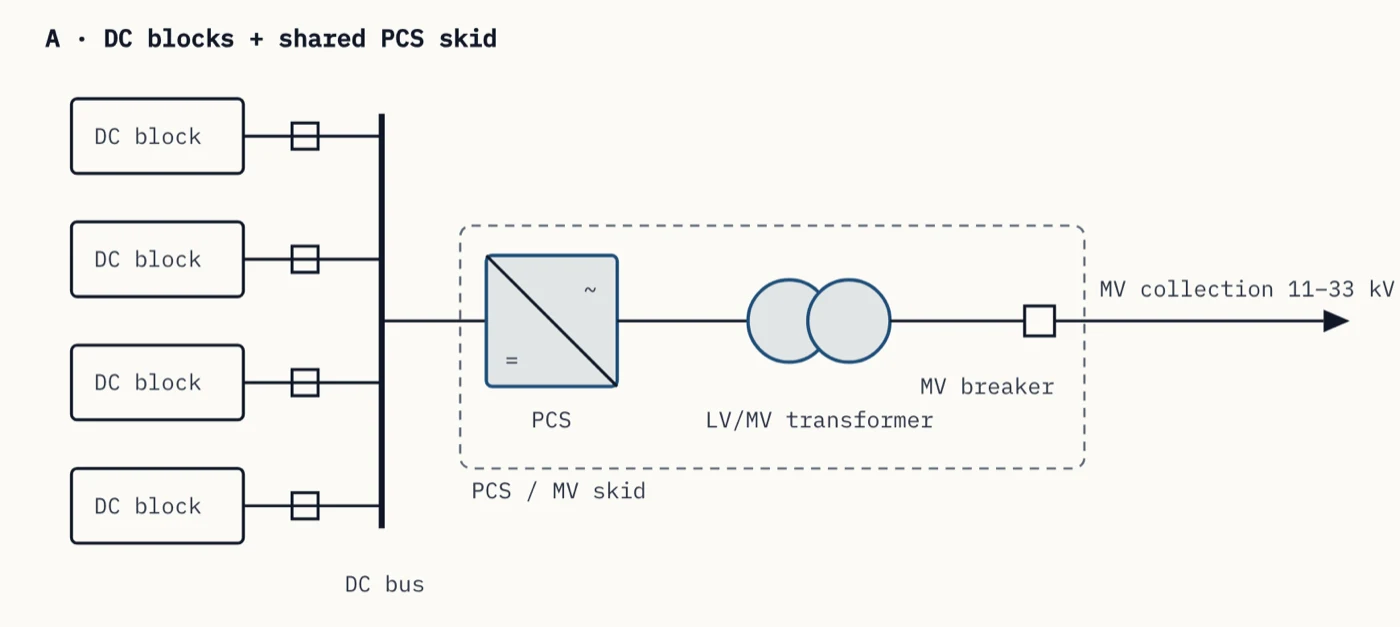
A block diagram explains the system — functional blocks and the connections between them. A single-line diagram(SLD, or one-line diagram) is the engineering document: it collapses the three-phase power path into a single drawn line and places every electrical element on it in order — battery blocks, DC disconnects and fuses, the power conversion system, the LV/MV step-up transformer with its winding configuration, MV switchgear, protection relays, CTs and PTs, metering, and grounding. Utilities, protection engineers, and AHJs review the SLD, not the block diagram.
The drawings below use standard symbol conventions (IEC 60617 / IEEE Std 315), simplified for teaching: protection, metering, grounding, and auxiliary power are omitted so the topology stays legible. Auxiliary power is small per hour and continuous, so it is easy to leave out of a drawing and out of a model — the auxiliary load estimator puts a number on it.
The three electrical archetypes
Strip away the branding and container count, and utility-scale BESS electrical design reduces to three one-lines. Everything else — single-row, dual-row, central block — is a site-layout variation of one of these.
One-line archetypes across the six standard site layouts
These are the placement patterns you see across utility-scale sites worldwide, drawn in plan view (white = battery container, accent = power-conversion equipment — the PCS/MVT skid, or in integrated products the built-in inverter and shared MV transformer). The archetype tag on each card names the one-line above that the layout implements; four of the six share the same one-line (archetype A). For the physical arrangement in full, see the BESS site-layout map.
Single-row, end-of-row PCS
One-line: archetype AOne row of battery containers, skid at the row end. The simplest cable plan and the easiest O&M access, but with the longest DC runs from the far container and the most land per MWh.
Dual-row, end-of-row PCS
One-line: archetype ATwo rows back-to-back sharing one skid. Cuts land per MWh by roughly a third versus a single row and shortens average DC runs; O&M and fire access run along the outer face of each row, so NFPA 855 unit separation sets the back-to-back gap.
Expansion-ready row
One-line: archetype AThe same electrical block with civil works and bus positions reserved for future containers. Augmentation capacity is designed in on day one — the SLD already carries the spare DC feeder positions, so adding energy later is a DC-side exercise; the AC one-line is untouched.
Distributed (string) PCS
One-line: archetype BA small PCS beside every container (or pair). DC runs shrink to metres, a converter fault takes out one container instead of a block, and dispatch is per-container — traded against many more units to install, network, and maintain.
Central PCS block (2×2 / 1×2)
One-line: archetype AContainers cluster around a central skid to form a repeatable power block — the whole plant is that block, copy-pasted along the MV feeder. DC runs stay balanced to every container and scaling stays clean; the block rating sets the plant's granularity. A 1×2 half-block — one container each side — fills odd row ends.
Modular AC block
One-line: archetype CFactory-integrated units (battery and inverter in one enclosure) parallel on LV and share a transformer. No field DC cabling and fast installation; energy and power scale together, so duration flexibility lives at the unit, not the site.
What changes between layouts — and what doesn't
The one-line barely moves between site layouts: archetypes A, B, and C cover essentially everything, and from the step-up transformer onward the drawing is the same in all three. What layout actually decides is cable quantity (DC runs from container to PCS are the cost that scales with row length — you can cost the AC and DC collection runs on the same route), augmentation space (whether adding containers later is a civil exercise or a redesign — the container pad quantities are where that shows up), O&M and fire access (corridor widths and separations per NFPA 855), and the fault domain — how much capacity one failed converter, transformer, or container takes offline. The interconnection performance obligations (IEEE 2800-2022) are set at the POI and do not change with layout.
That is why the layout decision belongs to the site plan and the SLD decision to the electrical design — and why reviewing them together, layout against one-line, catches the mismatches (a feeder daisy-chain that can't clear a block fault, a reserved bay with no spare DC position) that reviewing either alone misses. That paired read is most of what an independent design review is for.
Frequently asked
- What is a BESS single-line diagram?
- A BESS single-line diagram (SLD, also called a one-line diagram) is the formal electrical drawing of a battery storage plant. It represents the three-phase power path as a single line and shows every electrical element in order — battery DC blocks, disconnects and fuses, the PCS (inverter), the LV/MV step-up transformer, switchgear, protection, metering, and the connection to the medium-voltage collection system — using standard symbols. It is the document protection engineers, utilities, and AHJs review.
- Is a BESS single-line diagram the same as a schematic?
- In everyday use, yes — people search for a "BESS schematic diagram" or "electrical schematic" and mean the single-line diagram: the formal one-line drawing of the battery plant's electrical power path. Strictly, "schematic" is the broader term for any drawing that shows components and connections with standard symbols, while a single-line (one-line) diagram is the specific convention that collapses the three-phase power path onto one line. For a grid-scale BESS, the SLD is the schematic that matters for protection, interconnection, and permitting.
- What is the difference between a BESS block diagram and a single-line diagram?
- A block diagram answers "what are the parts and how do they connect" — functional blocks and arrows, no electrical formality. A single-line diagram is the engineering drawing of the AC/DC power path: exact bus topology, every breaker, fuse, transformer winding configuration, CT/PT, and protection element, drawn with standard symbols (IEC 60617 / IEEE Std 315). You explain a plant with a block diagram; you build, protect, and permit it from the SLD.
- How many battery containers connect to one PCS?
- It is set by ratings, not a rule: the PCS power (MW), the container energy (MWh), and the target duration. A common utility-scale pattern pairs one PCS/MV skid with two to six DC battery containers — for example, four 5 MWh containers on a 5 MW PCS make a 4-hour block. Higher C-rate systems use fewer containers per PCS; longer-duration systems use more.
- Do integrated AC-block units still need a transformer?
- Yes. An integrated AC block contains the batteries and the inverter in one enclosure, so its output is already AC — but at low voltage. It still needs a step-up transformer to reach the medium-voltage collection level (typically 11–33 kV). What integration removes is the field DC cabling between battery containers and a separate PCS skid, not the transformer.
- What symbols are used on a BESS single-line diagram?
- The standard graphic-symbol sets: IEC 60617 (international) or IEEE Std 315 (North America). The recurring BESS elements are the battery (long/short parallel lines), disconnect and fuse, the converter/inverter (box with AC and DC sides), the two-winding transformer (two overlapping circles), circuit breakers, current/voltage transformers for protection and metering, and the ground symbol.
References
Standards behind the drawing conventions and layout constraints on this page:
- IEC 60617 — Graphical symbols for diagrams
- IEEE Std 315 — Graphic Symbols for Electrical and Electronics Diagrams
- IEEE Std 2800-2022 — Interconnection and Interoperability of Inverter-Based Resources (IBRs) Interconnecting with Associated Transmission Electric Power Systems
- NFPA 855 — Standard for the Installation of Stationary Energy Storage Systems