MV Skid Structure
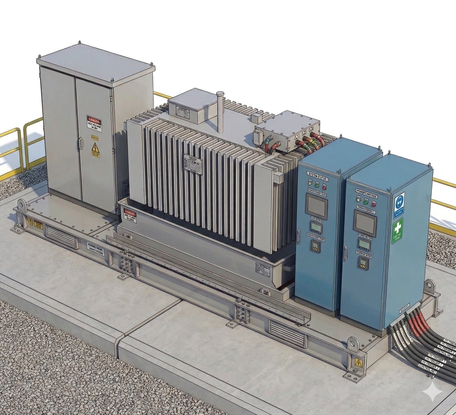
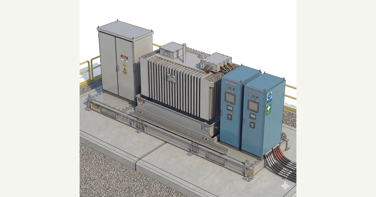
Major field interfaces on a skid-mounted conversion block.
Part of: the BESS block diagram — see every layer of the system in one place.
Download the MV Skid Structure diagram
Free to download and reuse — including commercially — under CC BY 4.0, with credit to BESS.engineer. Licence & attribution →
Browse all BESS diagrams →
What it shows
An MV skid is a single steel base carrying the medium-voltage conversion equipment that sits between a battery bank and the grid collection system. This visual maps one such skid with eight labelled markers: the Power Conversion System (PCS), an oil-cooled step-up transformer, MV switchgear, the LV connection kit, DC battery cables, MV cables, an oil retention tank, and the skid base and lifting frame. One PCS is drawn for clarity; a skid in service usually carries several, all feeding the one transformer. Hover or tap any marker to inspect that interface.
MV skid, MV station, power block: the same object
The assembly on this page is sold under at least five names, and the inconsistency is not between vendors so much as within them. Power Electronics markets it as the MV Skid Compact and calls it an MV station further down the same product page. Chint Power Systems sells the equivalent as a String PCS Station. Elsewhere the same three boxes on one base are a power skid, a power block or simply a PCS skid. None of it is a technical distinction: each describes a PCS, a step-up transformer and MV switchgear pre-assembled on a common base so a plant can be built from repeatable units. What does vary, and is worth asking about by name rather than by label, is whether the transformer ships mounted on the base or arrives loose for site assembly, whether MV switchgear is included or left to the collection contractor, and whether the quoted rating is the PCS output or the transformer. Two skids described in the same words can differ on all three.
Why it matters for BESS
The skid is where DC becomes grid-ready AC, and where the plant meets the grid code: the PCS is the device that has to hold up through a fault, so the ride-through envelope its grid code sets is a sizing input, not an afterthought. The PCS converts high-current DC from the battery enclosures into low-voltage AC (typically 400-800 V); the transformer then steps that up to medium voltage (11-33 kV) for export. Grouping these on one anchored, liftable base fixes equipment alignment and the service envelope, so a plant is built from repeatable conversion blocks rather than field-assembled one-offs. Every marker is a real interface an installer must terminate or maintain.
How to read it
Trace the power path right to left. DC battery connection cables enter the PCS DC input; the PCS outputs low-voltage AC through the LV connection kit into the transformer windings; the transformer steps up to medium voltage; MV switchgear provides the protected, isolatable AC interface; and MV cables carry that out to the collection system. Structural markers — the oil retention tank and the skid base with its lifting and anchoring points — sit beneath the electrical path.
Typical ranges
Ranges a practitioner would recognise across the market, not any one manufacturer's product. Per-unit and whole-skid ratings are separate rows on purpose: a figure given for one scope does not carry to the other.
| Item | Typical range on grid-scale BESS |
|---|---|
| PCS per skid | Usually severalThe diagram draws one for clarity. In service a skid carries several, all feeding the one transformer. |
| Skid rating (whole power block) | Typically 5–10 MVA total |
| Central PCS — rating per unit | 1–5 MVA per unit |
| String PCS — rating per unit | 230 or 430 kVA per unitTwo discrete unit sizes, not a range, and an alternative architecture rather than the bottom of the central one. String units stand at the battery enclosures and parallel on the LV bus, so that arrangement leaves this skid carrying the transformer and switchgear. |
| PCS DC input | 1050–1500 V DC1500 V is the system maximum rather than a continuous operating point. Full power is available over a narrower band that depends on the PCS and on its LV output voltage. |
| PCS LV output | 400–800 V AC |
| Conversion efficiency (PCS) | 98.5–99%Peak, and the PCS alone — not the skid, whose transformer adds its own loss. Efficiency is a function of voltage and load, so a peak figure describes one operating point rather than the envelope. |
| Step-up transformer | 5–15 MVAThe transformer's rating, not the skid's power rating — the distinction this page warns vendors blur. The same figure applies at both cooling stages, so ONAN and KNAN do not change it. |
| Transformer secondary | 11–33 kV |
| Transformer cooling | ONAN / KNAN |
| Tap changer | ±2.5% and ±5%Off-circuit taps, set with the transformer de-energised — not an on-load tap changer. |
| MV switchgear | Ring main unit (RMU), DV / DVC / DCV configuration |
| Short-circuit withstand | 25 kA for 3 sThe switchgear's short-time withstand rating. Not the plant's fault contribution, which is a different figure and is set by the converters. |
| Oil containment | Retention tank under the transformer |
| Footprint | 20 ft or 40 ft ISO-container equivalentA skid is an open base rather than an enclosure, and some exceed the nominal length slightly. |
| Mass | 15–25 tonnesThe complete skid as shipped, transformer and fluid included. Lifting weight is lower where the transformer ships drained and is filled on site. |
| Operating ambient | −30 to +55 °CAn operating range, not a full-power one: rated output typically holds to somewhere between 40 and 50 °C depending on the PCS, with derating above. Below about −25 °C usually needs a cold-climate option. |
| Altitude | To 2000 m without deratingThe reference altitude in the converter standard (IEC 62477-1), which is why PCS datasheets quote it. MV switchgear (IEC 62271-1) and transformers (IEC 60076) are referenced to 1000 m, so confirm per component — and note that altitude and maximum ambient derate against each other. |
Frequently asked
- What is an MV skid in a battery storage system?
- An MV (medium-voltage) skid is a steel base that carries the power-conversion equipment linking a battery bank to the grid — principally the PCS, a step-up transformer, and MV switchgear. It is delivered as one pre-assembled block so a plant can be built from repeatable units. On this skid the base also provides anchoring, lifting points, and the service envelope for maintenance.
- Why does the skid need a transformer if the PCS already makes AC?
- The PCS outputs low-voltage AC, typically 400-800 V, which is far too low to export efficiently across a plant. The oil-cooled transformer steps that up to medium voltage (11-33 kV) so current — and therefore cable losses — drops for the run to the collection system. The PCS handles DC-to-AC conversion; the transformer handles voltage level.
- What is the difference between the LV connection kit and the MV switchgear?
- They sit on opposite sides of the transformer. The LV connection kit links the inverter's low-voltage AC output to the transformer's input windings. The MV switchgear sits on the medium-voltage side, providing the protected AC interface for isolation, interlocking, and plant-level switching before the MV cables leave for the collection system.
- What is the oil retention tank for?
- The oil retention tank sits beneath the oil-cooled transformer and captures any oil leak or spill. It prevents environmental contamination of the site and satisfies containment requirements in site safety regulations. It is a structural and environmental interface, not part of the electrical path.
References
Standards and authoritative sources this visual is built on:
- UL 1741 — Inverters, Converters, Controllers and Interconnection System Equipment for Use With Distributed Energy Resources
- IEEE Std C57.12.00 — Standard for General Requirements for Liquid-Immersed Distribution, Power, and Regulating Transformers
- IEC 62271-200 — High-voltage switchgear and controlgear – Part 200: AC metal-enclosed switchgear and controlgear for rated voltages above 1 kV and up to and including 52 kV
- IEEE Std 1547 — Standard for Interconnection and Interoperability of Distributed Energy Resources with Associated Electric Power Systems Interfaces
- IEEE Std 980-2021 — IEEE Guide for Containment and Control of Oil Spills in Substations