BMS Three-Layer Structure
How the container BAU, rack BCUs, and module BMUs supervise a 5 MWh BESS.
Part of: the BESS block diagram — see every layer of the system in one place.
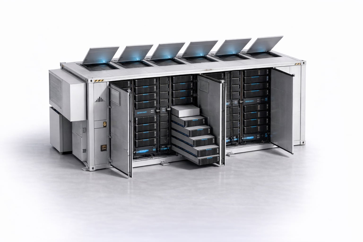
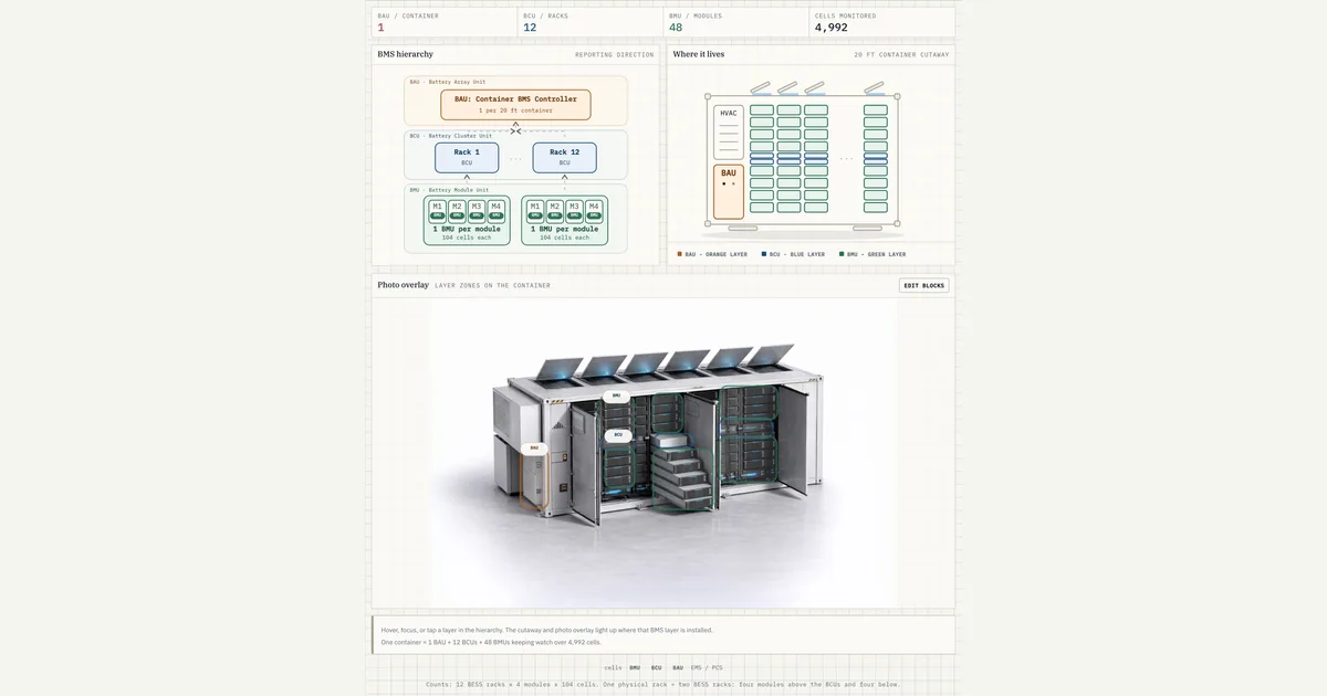
Hover, focus, or tap a layer in the hierarchy. The cutaway and photo overlay light up where that BMS layer is installed.
One container = 1 BAU + 12 BCUs + 48 BMUs keeping watch over 4,992 cells.
Counts: 12 BESS racks x 4 modules x 104 cells. One physical rack = two BESS racks: four modules above the BCUs and four below.
Download the BMS Three-Layer Structure diagram
Free to download and reuse — including commercially — under CC BY 4.0, with credit to BESS.engineer. Licence & attribution →
Browse all BESS diagrams →
What it shows
The BMS is the three-tier control network that supervises a 5 MWh battery container. At the top, one BAU (battery array unit) runs the whole container; beneath it, 12 BCUs (battery cluster units) each manage one BESS rack; at the base, 48 BMUs (battery module units) sit on individual modules, together watching 4,992 cells. Hover, focus, or tap any layer to highlight where it lives in the container and how it reports upward.
Why it matters for BESS
The BMS is the safety and telemetry backbone of a battery, and it only works because responsibility is split cleanly by tier. Cell-level measurement and balancing stay near the cells at the BMU; rack current, voltage, and contactor control live at the BCU; and only aggregated system-level SOC, SOH, and contactor state cross the BAU boundary to the EMS, PCS, HVAC, and fire suppression. That layering keeps thousands of cell channels manageable and defines where the BMS ends and plant-level control begins.
How to read it
Follow the chain bottom-up. Each of the 48 BMUs measures its module's cell voltages and temperatures (about 104 cells per module) and streams them to its BCU. Each of the 12 BCUs collects four BMUs' data, measures rack voltage and current, drives rack contactors and pre-charge, and reports to the BAU. The single BAU aggregates all 12 racks into one system view and talks to the outside world. Note the packaging: one physical rack holds two BESS racks (two BCUs), four modules above and four below.
Frequently asked
- What is the difference between BAU, BCU, and BMU in a battery management system?
- They are the three tiers of the BMS. The BMU (battery module unit) sits on each module and measures individual cell voltages and temperatures while balancing cells. The BCU (battery cluster unit) manages one rack, collecting BMU data and measuring rack voltage and current. The BAU (battery array unit) is the top level: one per container, aggregating system SOC and SOH and interfacing with the EMS and PCS.
- How many BMS controllers and cells are in a BESS container?
- In this 5 MWh 20 ft container there is 1 BAU, 12 BCUs, and 48 BMUs, together supervising 4,992 cells. One physical rack houses two BESS racks, so it carries two BCUs, and each module carries one BMU covering roughly 104 cells. The counts multiply cleanly: 48 modules of about 104 cells give the 4,992 total.
- Where does the BMS end and the EMS or PCS begin?
- The boundary sits at the BAU. The BAU is the only layer that talks outward, communicating system-level SOC, SOH, and contactor state to the EMS, PCS, HVAC, and fire suppression. Everything below it, cell measurement at the BMU and rack control at the BCU, stays internal to the battery and never speaks directly to plant-level controllers.
- What does cell balancing do and which BMS layer handles it?
- Cell balancing evens out small state-of-charge differences between series-connected cells so the weakest cell does not limit the whole string. In this architecture it is handled at the BMU, the bottom layer closest to the cells, using passive balancing. The BMU measures each cell's voltage and temperature and balances locally, then streams the readings up to its BCU.
- What does the BMS protect against, and which layer opens the contactors?
- The BMS trips on a core set of fault conditions: cell over- and under-voltage, over-current including short circuit, over- and under-temperature, and a battery-to-chassis isolation (insulation) fault. It also watches for the early electrical and thermal signatures of runaway, mainly a rapid cell-voltage drop and a fast temperature rise, while off-gas is caught by dedicated gas detection tied to fire suppression. Sensing sits at the lower tiers: the BMU measures each cell's voltage and temperature, and the BCU measures rack current and voltage. Opening the contactors happens at the BCU, which drives its own rack contactors, so a detected fault physically disconnects the affected rack rather than just raising an alarm.
References
Standards and authoritative sources this visual is built on:
- IEEE Std 2686-2024 — IEEE Recommended Practice for Battery Management Systems in Stationary Energy Storage Applications
- UL 1973 — Standard for Batteries for Use in Stationary and Motive Auxiliary Power Applications (BMS functional and protection requirements)
- IEC 62933-5-2 — Electrical energy storage (EES) systems, Part 5-2: Safety requirements for grid-integrated EES systems — electrochemical-based systems
- NFPA 855 — Standard for the Installation of Stationary Energy Storage Systems (BMS role and interface with fire suppression and HVAC)