BESS Site Layout & Component Map
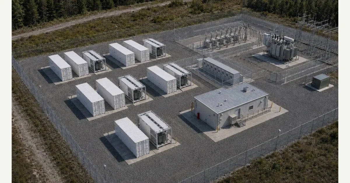
A site-level view of repeated energy stations and the path to grid interconnection.
Part of: the BESS block diagram — see every layer of the system in one place.
Download the BESS Site Layout & Component Map diagram
Free to download and reuse — including commercially — under CC BY 4.0, with credit to BESS.engineer. Licence & attribution →
Browse all BESS diagrams →
What it shows
The BESS Site Component Map is an annotated aerial view of a grid-scale battery plant, with nine interactive blocks tracing the power path from cells to the grid. It repeats an Energy Station — battery containers plus a PCS/MV skid — several times, then feeds MV combiner switchgear, a main step-up transformer, an HV switchyard, and the grid point of interconnection. A control building and ancillary transformer sit off the main path.
Why it matters for BESS
A battery plant is not one machine but a repeated build unit wired into a shared collection and interconnection spine. The Energy Station is the module that repeats to scale capacity; everything downstream of the MV combiner is a single trunk sized for the whole site. Seeing where voltage changes — DC at the battery bus, LV inside the skid, MV across collection, HV from the GSU onward — is how engineers reason about protection zones, losses, and which equipment is shared versus multiplied.
How to read it
Follow the chain left to right: battery containers (DC) into the PCS/MV skid, which inverts DC to LV AC and steps it up to MV. MV feeders from every station converge at the combiner switchgear, the GSU steps MV up to transmission voltage, and the HV switchyard lands the line at the grid POI gantry. Colours mark voltage class — DC, MV AC, HV AC. Set Flow to Discharge or Charge to animate power along the path, or use Walk the path for a guided tour of each block.
Frequently asked
- What are the main components of a BESS site?
- A grid-scale battery site is built from repeated energy stations — each combining battery containers with a PCS/MV skid — feeding a shared spine of MV combiner switchgear, a main step-up (GSU) transformer, an HV switchyard, and the grid point of interconnection. A control building housing SCADA/EMS and protection, plus an ancillary transformer for station auxiliaries, sit off the main power path.
- How does the PCS/MV skid repeat across a BESS site?
- A grid-scale site is a repeated pattern of energy stations, each built around one PCS/MV skid feeding a shared medium-voltage collection network that runs to the point of interconnection. Scaling the plant means adding more skid-plus-container stations, not enlarging one — the skid is the modular power-conversion block the whole site multiplies.
- What does a GSU transformer do at a BESS site?
- The GSU, or main step-up transformer, raises the site's MV collection voltage to transmission (HV) level so the plant can export to the grid. It sits between the MV combiner switchgear and the HV switchyard. In a battery project it works in both directions — stepping down transmission voltage to MV when the site charges.
- What is the point of interconnection (POI) for a battery project?
- The point of interconnection is where the plant's transmission line physically lands at the grid — here the takeoff gantry, the terminal structure after the HV switchyard. It is the contractual and electrical boundary between the BESS and the network, and the point where the utility typically defines metered export/import limits and protection requirements.
References
Standards and authoritative sources this visual is built on:
- IEEE 2800-2022 — IEEE Standard for Interconnection and Interoperability of Inverter-Based Resources (IBRs) Interconnecting with Associated Transmission Electric Power Systems
- IEEE 1547-2018 — IEEE Standard for Interconnection and Interoperability of Distributed Energy Resources with Associated Electric Power Systems Interfaces
- IEC 62933-2-1:2018 — Electrical Energy Storage (EES) Systems — Part 2-1: Unit Parameters and Testing Methods (General Specification)
- DOE/EPRI Electricity Storage Handbook in Collaboration with NRECA (SAND2015-1002) — Battery Storage System Architecture, Power Conversion, Transformers and Grid Interconnection