Cell Losses & Efficiency
How C-rate and internal resistance separate cell voltage curves and reduce RTE.
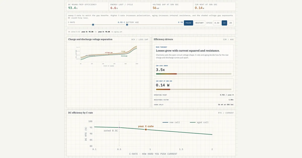
Chemistry sets the open-circuit voltage shape. C-rate and aging decide how far the real charge and discharge curves pull apart.
Download the Cell Losses & Efficiency diagram
Free to download and reuse — including commercially — under CC BY 4.0, with credit to BESS.engineer. Licence & attribution →
Browse all BESS diagrams →
What it shows
Cell losses are the fraction of a battery cell's stored energy dissipated as heat rather than returned to the circuit, set mostly by C-rate and internal resistance. This visual plots one cell's charge and discharge voltage curves across state of charge, shading the gap between them, while a second panel traces DC round-trip efficiency against C-rate for a fresh and an aged cell. Sweep C-rate (0.1C-2C) and age to watch the gap, I2R heat, and RTE move.
Why it matters for BESS
Round-trip efficiency is a headline warranty and revenue number, and it starts at the cell. Because loss scales with current, a battery run harder (higher C-rate) returns proportionally less of what it stored, and as internal resistance climbs with age the same current dissipates more heat. This visual isolates the DC cell-level loss before any PCS, auxiliary, or thermal-management loss is added, so you can see where the efficiency budget is actually spent.
How to read it
On the left, the charge curve sits above the discharge curve; the shaded band between them is the ohmic voltage gap, widest at the SoC extremes and marked at 50% SoC. Do not try to reconcile that gap with the round-trip figure arithmetically: the gap is cell ohmic loss alone, while the RTE panel carries the whole DC round trip, so the RTE is the lower of the two and deliberately so. Higher C-rate or greater age pushes the two curves apart. On the right, follow the DC round-trip efficiency curve versus C-rate: at rated 0.5C on a year-0 cell it reads 95%, and it falls as you move right or select an older cell. The readouts report energy lost per cycle, the 50%-SoC voltage gap in mV, and I2R heat in watts.
Frequently asked
- Why does round-trip efficiency drop at higher C-rate?
- Because loss is ohmic: the voltage the cell must overcome to push current is proportional to current times internal resistance. At higher C-rate the charge voltage rises and the discharge voltage sags, widening the gap between them, so more of the stored energy is spent as I2R heat instead of being returned. In this model a cell at rated 0.5C reads 95% DC RTE and falls as you push toward 2C.
- What is the voltage gap at 50% SoC?
- It is the difference between the charge and discharge terminal voltage at the same state of charge, driven by current flowing through internal resistance. The gap is the direct cause of round-trip loss: energy put in at the higher charge voltage comes back out at the lower discharge voltage. It is smallest in the mid-SoC plateau and widens at the extremes, and the visual reports it in millivolts at 50% SoC.
- How does cell age affect efficiency?
- Aging raises internal resistance, so the same current produces a larger voltage gap and more I2R heat, lowering round-trip efficiency. The visual shows this as growing separation between the year-0 and aged efficiency curves, and reports the aging loss in efficiency points at the rated 0.5C C-rate. This is a resistance effect distinct from capacity fade, though both progress with cycling and calendar life.
- Is this DC round-trip efficiency or the full system RTE?
- This is DC cell-level round-trip efficiency only. It captures the charge-then-discharge loss inside the cell from internal resistance, before any PCS conversion, auxiliary, or thermal-management losses. Full AC-side system RTE at the point of interconnection is lower, because the PCS and station auxiliaries add their own losses on top of this DC figure.
References
Standards and authoritative sources this visual is built on:
- IEC 62933-2-1:2018 — Electrical energy storage (EES) systems, Part 2-1: Unit parameters and testing methods — General specification (defines DC/AC round-trip efficiency and its measurement)
- Battery Test Manual for Electric Vehicles / Stationary Applications — Hybrid Pulse Power Characterization (HPPC) procedure defining cell DC internal resistance and ohmic (I2R) loss measurement
- IEEE Std 1679-2020 — IEEE Recommended Practice for the Characterization and Evaluation of Energy Storage Technologies in Stationary Applications (cell resistance growth, efficiency vs. C-rate and age)