Plant Control Command Path
How a grid or market instruction becomes a safe BESS operating command.
Download the Plant Control Command Path diagram
Free to download and reuse — including commercially — under CC BY 4.0, with credit to BESS.engineer. Licence & attribution →
Browse all BESS diagrams →
What it shows
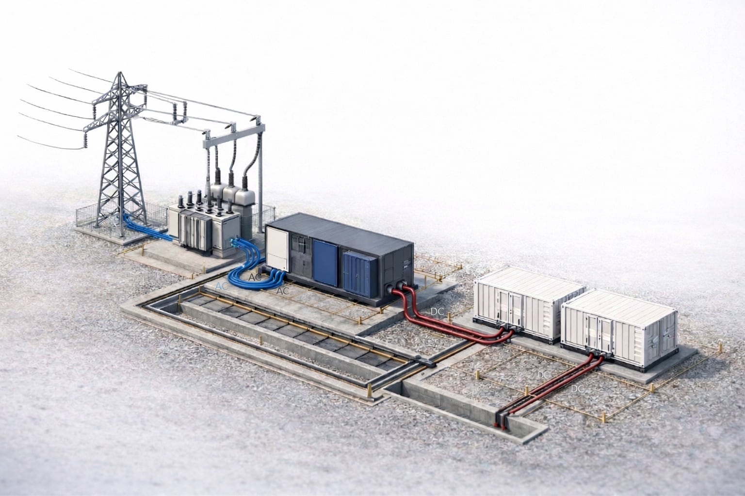
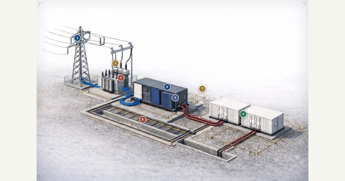
The plant control command path is the chain that turns a grid or market instruction into a safe, executed BESS operating point. This visual maps eight parts across a real energy-station photo, grouped into five layers: Command Path, PCS Response, BMS Limits, Telemetry and Metering, and Protection and Interlocks. Hover or tap a marker to follow how a remote dispatch instruction reaches the plant controller, becomes a PCS command, and returns as measured feedback.
Why it matters for BESS
No dispatch instruction reaches the battery unfiltered. A market or operator setpoint only becomes real power if the plant controller (PPC) can translate it into active and reactive references, the PCS can execute it within inverter ratings and grid sync, the BMS reports enough headroom in current, voltage, temperature, and state of charge, and protection permissives allow the plant to stay online. This visual makes those scope boundaries — EMS, PPC, PCS, BMS — explicit, which is where most control disputes and safe-state failures originate.
How to read it
Follow the command downstream: a remote dispatch instruction (1) sets requested behavior; the plant controller (4) turns it into P and Q references with a ramp rate; the PCS (5) executes charge or discharge within its ratings and grid sync. Then read the feedback and guardrails upstream: BMS operating limits (6) constrain SOC and current, POI metering (2) confirms delivered power for controls and settlement, the historian (7) records it, and grid permissives (3) plus the site trip chain (8) decide whether the plant may run or must resolve to a safe state.
Frequently asked
- What is the difference between EMS, PPC, PCS, and BMS in a BESS?
- They are four distinct control scopes. The EMS (energy management system) and remote dispatch decide what the plant should do; the PPC (power plant controller) translates that into real-time active and reactive power references with a ramp rate; the PCS (power conversion system) executes charge or discharge within inverter ratings and grid synchronization; and the BMS (battery management system) reports the current, voltage, temperature, and state-of-charge limits that constrain what any of the above can actually command.
- How does a market or grid instruction become an actual BESS command?
- A remote dispatch instruction defines the requested charge, discharge, standby, or grid-support behavior. The plant controller converts that target into active and reactive power references for the conversion blocks. The PCS then executes it while respecting inverter ratings, grid sync, derating, and local protection status — but only within the operating limits the BMS reports. POI metering confirms the delivered result back to controls and settlement.
- Can the BMS or protection override a commanded setpoint?
- Yes. The BMS reports allowable current, voltage, temperature, state of charge, and alarms that constrain plant dispatch, so a commanded power that exceeds those limits is curtailed regardless of what was requested. Separately, protection relays and interlocks set permissives that decide whether the plant may connect, stay online, or trip — and the site-level trip chain (E-stops, fire signals, communication loss) must resolve to a predictable safe state.
- What is a power plant controller (PPC) responsible for?
- The PPC sits between dispatch and the inverters. It translates plant-level dispatch targets into the real-time active-power (P) and reactive-power (Q) references the PCS blocks execute, and it governs how fast those references change through ramp-rate control. It works against measured feedback from POI metering, so the delivered power tracks the requested setpoint rather than the raw command.
References
Standards and authoritative sources this visual is built on:
- IEEE Std 2800-2022 — IEEE Standard for Interconnection and Interoperability of Inverter-Based Resources (IBRs) Interconnecting with Associated Transmission Electric Power Systems
- IEEE Std 1547-2018 — IEEE Standard for Interconnection and Interoperability of Distributed Energy Resources with Associated Electric Power Systems Interfaces
- IEC 62933-2-1:2018 — Electrical Energy Storage (EES) Systems — Part 2-1: Unit Parameters and Testing Methods — General Specification
- Reliability Guideline: BPS-Connected Inverter-Based Resource Performance