Power Factor Triangle
A practical P-Q triangle for seeing how apparent power divides into MW, MVAr, and compensation to a target PF.
Download the Power Factor Triangle diagram
Free to download and reuse — including commercially — under CC BY 4.0, with credit to BESS.engineer. Licence & attribution →
Browse all BESS diagrams →
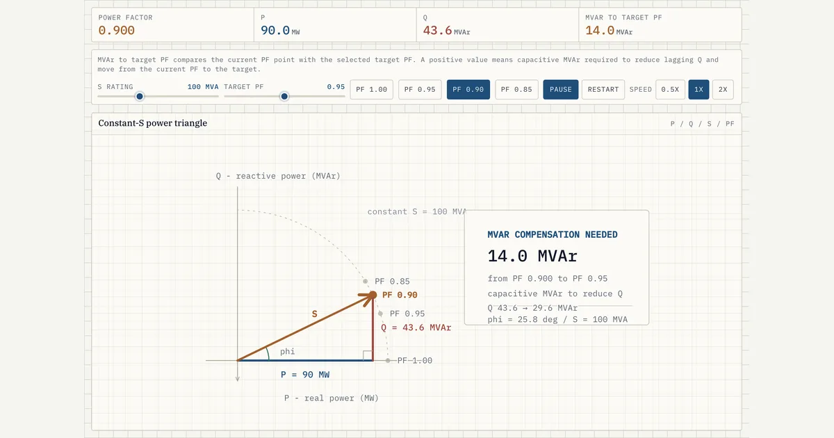
What it shows
For a fixed apparent power S (MVA), the triangle shows how much goes to real power P (MW) versus reactive power Q (MVAr) at a given power factor. Moving the target power factor shows the reactive compensation required — the MVAr you must add or absorb to move from the present operating point to the target.
Why it matters for BESS
Interconnection agreements specify a power-factor range (often 0.95 leading to 0.95 lagging) at the point of interconnection. This triangle is how engineers translate that requirement into MVAr capability and confirm the PCS rating leaves enough headroom for both real-power dispatch and reactive support.
Frequently asked
- How do you calculate reactive power for a target power factor?
- From P and the target power factor cos φ, the required reactive power is Q = P·tan(φ). The compensation needed is the difference between that target Q and the present Q.
- Why is power factor important for battery storage?
- Grid operators require BESS plants to hold power factor within a band and often to provide voltage support via reactive power. Power factor sizing determines how much of the inverter kVA must be reserved for kVAr rather than kW.
- What is the difference between leading and lagging power factor?
- Lagging power factor is inductive: the load or inverter absorbs reactive power (Q), which tends to depress the local voltage — the behaviour of motors and transformers. Leading is capacitive: the device injects reactive power, which tends to raise voltage. Watch the reference frame — the physical direction of Q is fixed, but its sign and the lead/lag label flip between load and generator conventions, so a device absorbing VArs is "lagging" as a load yet "leading" (underexcited) as a generator. A BESS PCS is a four-quadrant converter, so it can sit anywhere in its P–Q capability — leading or lagging, absorbing or injecting reactive power — to hold the interconnection's power-factor band and support voltage.
References
Standards and authoritative sources this visual is built on:
- IEEE Std 2800-2022 — IEEE Standard for Interconnection and Interoperability of Inverter-Based Resources (IBRs) Interconnecting with Associated Transmission Electric Power Systems (reactive power capability and power factor requirements at the point of interconnection)
- IEEE Std 1547-2018 — IEEE Standard for Interconnection and Interoperability of Distributed Energy Resources with Associated Electric Power Systems Interfaces (reactive power and power factor requirements)
- IEEE Std 1459-2025 — IEEE Standard Definitions for the Measurement of Electric Power Quantities Under Sinusoidal, Nonsinusoidal, Balanced, or Unbalanced Conditions (definitions of real power P, reactive power Q, apparent power S, and power factor)
- FERC Order No. 827 — Reactive Power Requirements for Non-Synchronous Generation (0.95 leading to 0.95 lagging power-factor range for newly interconnecting inverter-based generation)