Floating Neutral (3-Wire / Delta)
Without a neutral the three line currents are forced to sum to zero, so three-phase imbalance reappears as a shift of the neutral-point voltage — and an overvoltage on lightly loaded or open phases.
Download the Floating Neutral (3-Wire / Delta) diagram
Free to download and reuse — including commercially — under CC BY 4.0, with credit to BESS.engineer. Licence & attribution →
Browse all BESS diagrams →
What it shows
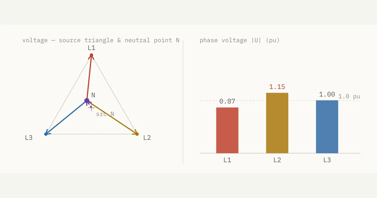
A floating neutral is the load's neutral point in a three-wire (delta or ungrounded-wye) system that has no conductor tying it back to the source. This visual fixes the balanced source phase-voltage triangle and lets you unbalance the three loads by angle and magnitude. With no return path the line currents must sum to zero, so the load neutral point N slides off centre by the neutral-shift voltage V_N (Millman's theorem), and a bar chart reads each phase voltage against the 1.0 pu nominal.
Why it matters for BESS
Three-wire connections are common on the medium-voltage side of a BESS — delta-connected PCS transformer windings and ungrounded or high-impedance-grounded arrangements have no neutral return. When phase loads or currents go unbalanced, the imbalance cannot escape as neutral current; it reappears as a neutral-point shift that raises the voltage on the lightly loaded or open phase. That overvoltage stresses insulation, surge arresters, and filter capacitors, and it changes how ground faults are detected.
How to read it
Follow the neutral point N. Balanced, it sits on the source neutral, all three bars read 1.00 pu, and status shows balanced. Add imbalance and N slides off along the dashed V_N vector; the vectors from N to each line are the unbalanced phase voltages, and any bar above 1.05 pu turns red. The chips track neutral shift V_N, max phase V, and neutral I_N (fixed at 0.00 pu). Run Drop L3: V_N reaches 0.50 pu and the open phase swings to a 1.50 pu terminal voltage.
Frequently asked
- What is a floating neutral?
- A floating neutral is the neutral point of a three-wire system — a delta or ungrounded-wye arrangement — that has no conductor connecting it to the source neutral. Because there is no return path, the three line currents are forced to sum to zero (ΣI = 0). The neutral point is free to move, and its potential is set by the load imbalance rather than held at the source reference.
- Why does a floating neutral cause overvoltage?
- With no neutral return, imbalance cannot flow away as neutral current, so it instead displaces the load neutral point by a shift voltage V_N. That shift adds to the source voltage on the lightly loaded or open phase, pushing its phase voltage above 1.0 pu. In this visual, dropping L3 shifts the neutral by 0.50 pu and drives the open phase to a 1.50 pu terminal overvoltage.
- How does a 3-wire (floating neutral) system differ from a 4-wire one under imbalance?
- In a 4-wire wye system the neutral conductor carries the vector sum of the line currents, so imbalance shows up as neutral current while the phase voltages stay balanced — a dropped phase leaves a full 1.00 pu in the neutral. In a 3-wire system there is no such path: the same dropped phase produces zero neutral current but a 0.50 pu neutral-point shift and a 1.50 pu overvoltage on the open phase.
- What is the neutral-point shift voltage (Millman's theorem)?
- The neutral-point shift is the voltage V_N between the source neutral and the floating load neutral, calculated by Millman's theorem from the admittance-weighted sum of the phase voltages. It is zero when loads are balanced and grows with imbalance. In the visual it is the dashed vector displacing point N, reported as the neutral shift V_N chip in per-unit.
References
Standards and authoritative sources this visual is built on:
- IEEE Std 142 (Green Book) — IEEE Recommended Practice for Grounding of Industrial and Commercial Power Systems
- IEEE Std C62.92.1 — IEEE Guide for the Application of Neutral Grounding in Electrical Utility Systems, Part I: Introduction
- IEEE Std 141 (Red Book) — IEEE Recommended Practice for Electric Power Distribution for Industrial Plants