Phase Shift and Power
How current phase shift changes useful work power, reactive exchange, and total apparent power.
current lags voltage by 30.0 deg
absorbing VARs / PF 0.866
Download the Phase Shift and Power diagram
Free to download and reuse — including commercially — under CC BY 4.0, with credit to BESS.engineer. Licence & attribution →
Browse all BESS diagrams →
What it shows
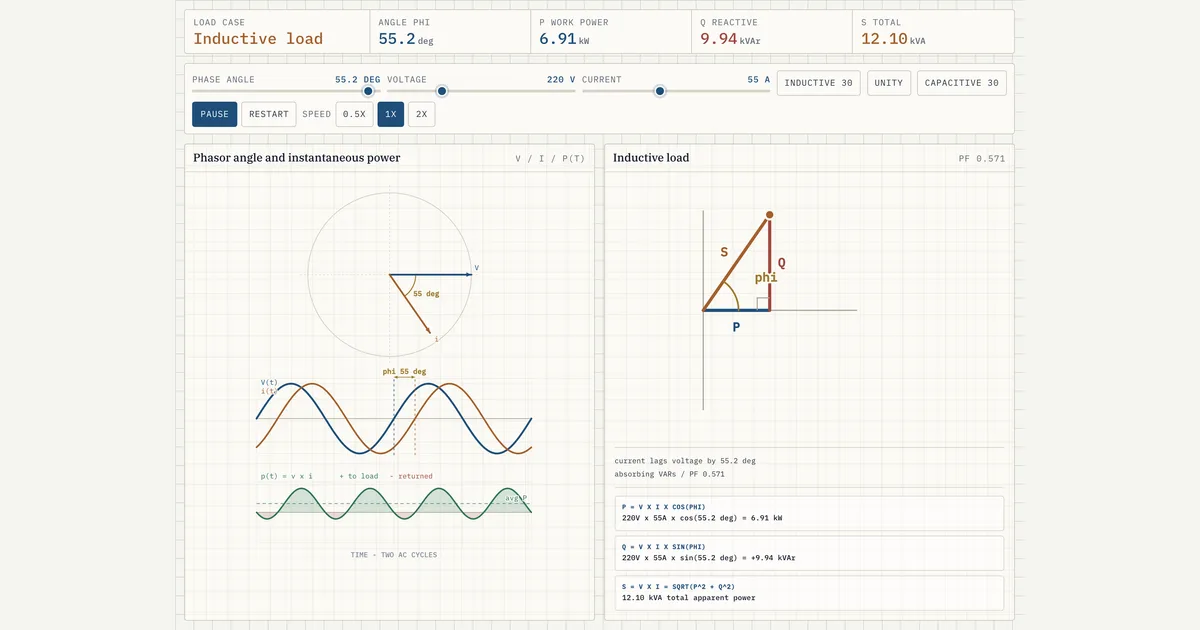
Phase shift is the angle (phi) between the AC voltage and current waveforms, and it decides how apparent power splits into useful work and reactive exchange. This visual sweeps phi from -90 to +90 degrees on a 220 V, 55 A example and traces the voltage and current waves, the instantaneous power curve, and a P-Q-S triangle. As phi changes, real power P (kW), reactive power Q (kVAr), apparent power S (kVA), and power factor all move together.
Why it matters for BESS
A grid-scale inverter (PCS) does not just push watts — it is commanded to a real and reactive setpoint, and the phase angle between its output voltage and current is what sets that split. Absorbing VARs (inductive, lagging) or supplying VARs (capacitive, leading) is how a battery supports voltage without moving net energy. Because apparent power S sizes the PCS and transformer, understanding how Q eats into the kVA budget at a fixed S is central to reactive-power dispatch and grid-code compliance.
How to read it
Set the angle or let it sweep. At phi = 0 the current is in phase with voltage, PF = 1, and all of S is real power P with no VAR exchange. Push phi positive and the current lags (inductive, absorbing VARs); push it negative and the current leads (capacitive, supplying VARs). On the power wave, green lobes are energy flowing to the load and red lobes are energy returned to the source — their net is P. The triangle holds S fixed while P (cos phi) and Q (sin phi) trade off, so S^2 = P^2 + Q^2 always closes.
Frequently asked
- What is the difference between real, reactive, and apparent power?
- Real power P (kW) is the average power that does useful work; reactive power Q (kVAr) sloshes back and forth between source and load without net work; and apparent power S (kVA) is the vector sum of the two. They are related by S^2 = P^2 + Q^2, and power factor is PF = P/S = cos(phi), where phi is the phase angle between voltage and current.
- Does a leading or lagging current mean the load is inductive or capacitive?
- A lagging current (phi positive) means an inductive load that absorbs reactive power (VARs) — the current peak arrives after the voltage peak. A leading current (phi negative) means a capacitive load that supplies VARs, with the current peak arriving first. In this visual, positive angles are labelled inductive and absorbing VARs; negative angles are capacitive and supplying VARs; at phi = 0 the current is in phase and there is no VAR exchange.
- Why does reactive power reduce how much real power an inverter can deliver?
- Because a PCS is rated in apparent power (kVA), and S^2 = P^2 + Q^2. At a fixed S, every kVAr of reactive power Q you command reduces the real power P available, since P = S*cos(phi). So an inverter dispatching VARs for voltage support has less headroom for real (MW) throughput — the phase angle sets exactly how the fixed apparent-power budget is divided.
- How is power factor related to the phase angle?
- Power factor equals the cosine of the phase angle: PF = cos(phi). At phi = 0, PF = 1 and all apparent power is real work. As phi grows, PF falls: at 60 degrees PF = cos 60 deg = 0.5, so real power is half of S while reactive power is S x sin 60 deg, about 87% of S. At the visual's +/-90 degree limits PF reaches 0 — the load is purely inductive or capacitive, P is zero, and all of S is reactive power. The sign of phi (lead versus lag) tells you whether the reactive power is being supplied or absorbed.
References
Standards and authoritative sources this visual is built on:
- IEEE Std 1459-2025: IEEE Standard Definitions for the Measurement of Electric Power Quantities Under Sinusoidal, Nonsinusoidal, Balanced, or Unbalanced Conditions
- IEEE Std 2800-2022: IEEE Standard for Interconnection and Interoperability of Inverter-Based Resources (IBRs) Interconnecting with Associated Transmission Electric Power Systems (reactive power capability and power factor requirements)
- IEEE Std 1547-2018: IEEE Standard for Interconnection and Interoperability of Distributed Energy Resources with Associated Electric Power Systems Interfaces (constant power factor and voltage-reactive power modes)
- Reliability Guideline: Reactive Power Planning