Reactive Power Direction
A phase-angle view of how P, Q, S, and power factor move together.
Download the Reactive Power Direction diagram
Free to download and reuse — including commercially — under CC BY 4.0, with credit to BESS.engineer. Licence & attribution →
Browse all BESS diagrams →
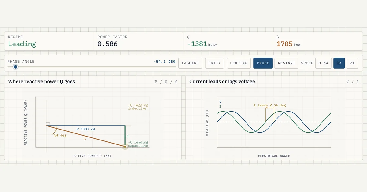
What it shows
Active power P (kW), reactive power Q (kVAr), and apparent power S (kVA) form a right triangle: S² = P² + Q². The angle φ between voltage and current sets the split. When current lags voltage the load absorbs reactive power (inductive); when it leads, it supplies reactive power (capacitive). Power factor is cos φ = P/S.
Why it matters for BESS
A grid-scale inverter is sized in kVA but paid mostly for kW — and grid codes require it to absorb or supply kVAr on demand. Seeing P, Q, and S as one triangle makes the trade-off explicit: every kVAr of reactive support eats into the kW headroom of the same kVA rating.
Frequently asked
- What is the difference between active, reactive, and apparent power?
- Active power (kW) does real work; reactive power (kVAr) shuttles energy back and forth to sustain magnetic and electric fields; apparent power (kVA) is the vector sum the equipment must actually carry.
- What does lagging vs leading power factor mean?
- Lagging means current lags voltage and the load is net inductive (absorbing reactive power); leading means current leads voltage and the load is net capacitive (supplying reactive power).
- Can a BESS provide reactive power when it is neither charging nor discharging?
- Yes. At P ≈ 0 the whole kVA rating is free for reactive power, so the PCS can source or sink kVAr up to its full apparent-power rating — effectively a STATCOM for voltage support. The limit is the inverter's P–Q capability curve and thermal rating, not the battery. Because reactive current only circulates in and out of phase, the state of charge barely moves beyond conversion losses.
References
Standards and authoritative sources this visual is built on:
- IEEE Std 1459-2025 — IEEE Standard Definitions for the Measurement of Electric Power Quantities Under Sinusoidal, Nonsinusoidal, Balanced, or Unbalanced Conditions
- IEEE Std 2800-2022 — IEEE Standard for Interconnection and Interoperability of Inverter-Based Resources (IBRs) Interconnecting with Associated Transmission Electric Power Systems (reactive power capability and power factor requirements)
- IEEE Std 1547-2018 — IEEE Standard for Interconnection and Interoperability of Distributed Energy Resources with Associated Electric Power Systems Interfaces (reactive power and power factor provisions)
- Reactive Power Planning — NERC Reliability Guideline on reactive power capability and voltage support from generating resources