Current Harmonics and THD
How nonlinear current components distort the fundamental waveform and show up as harmonic spectrum and THD.
Download the Current Harmonics and THD diagram
Free to download and reuse — including commercially — under CC BY 4.0, with credit to BESS.engineer. Licence & attribution →
Browse all BESS diagrams →
What it shows
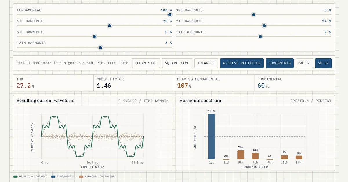
Current harmonics are sinusoidal components at integer multiples of the fundamental frequency that, when summed, distort an otherwise clean current wave. This control visual builds that sum live: a 1st-order fundamental plus odd harmonics (3rd, 5th, 7th, 9th, 11th, 13th), each set as a percentage of the fundamental. You see the resulting waveform, a spectrum bar per order, and three derived numbers: total harmonic distortion (THD), crest factor, and peak-vs-fundamental. Presets cover a clean sine, square wave, triangle, and 6-pulse rectifier.
Why it matters for BESS
A battery's power conversion system (PCS) is a switching converter, so its AC current is never perfectly sinusoidal. Injected harmonics heat transformers, trip protection, and distort grid voltage, which is why interconnection agreements hold inverters to harmonic limits under IEEE 519. The 6-pulse rectifier preset, dominated by the 5th, 7th, 11th, and 13th orders, is the classic nonlinear signature that filter design and PCS controls are built to suppress. For current, those limits are written as total demand distortion (TDD) plus per-order limits, TDD being the harmonic current as a percentage of maximum demand load current and closely related to the THD this visual builds up.
How to read it
Pick a preset or drag individual harmonic orders and watch three things move together. The waveform shows how each added order sharpens or flattens the shape. The spectrum plots each harmonic as a bar relative to the 100% fundamental. THD is the RMS of all the harmonics divided by the fundamental, so a clean sine reads near 0% and a square wave reads high. Crest factor is peak divided by RMS; a pure sine sits at about 1.41.
Frequently asked
- What is total harmonic distortion (THD)?
- THD is the root-sum-square of all the harmonic components expressed as a percentage of the fundamental. In this visual it is computed as the square root of the sum of the squared harmonic amplitudes divided by the fundamental amplitude. A clean sine has no harmonics and reads near 0%; a square wave, which stacks many odd orders, reads high.
- Why are only odd harmonics shown?
- Symmetric AC loads and converters produce a waveform whose positive and negative half-cycles are mirror images, and that half-wave symmetry cancels the even harmonics. What remains are the odd orders, which is why this tool exposes the 3rd, 5th, 7th, 9th, 11th, and 13th. A 6-pulse rectifier further suppresses the 3rd and 9th, leaving the 5th, 7th, 11th, and 13th as its signature.
- What is crest factor and why does it matter?
- Crest factor is the ratio of a waveform's peak to its RMS value. A pure sine wave has a crest factor of about 1.41 (the square root of 2). Harmonics that add sharp peaks raise the crest factor, which stresses insulation and semiconductor devices and can cause meters or protection that assume a sinusoid to misread the current.
- How does this relate to IEEE 519?
- IEEE 519 is the standard that sets harmonic current and voltage distortion limits at the point of common coupling. Its current limits are written as total demand distortion (TDD), the harmonic current as a percentage of the maximum demand load current, plus individual-order limits, while its voltage limits use THD. This visual computes THD relative to the present fundamental, which approaches TDD at full load. For a BESS, the PCS and any filters must keep injected current harmonics within those limits, so understanding how orders sum into THD is the first step to meeting them.
- What are the actual IEEE 519 harmonic limits a BESS has to meet?
- IEEE 519-2022 puts the inverter's obligation on current, written as total demand distortion (TDD) that scales with the short-circuit ratio Isc/IL at the point of common coupling: a weak connection (Isc/IL below 20) is held to 5% TDD, rising to 20% for the stiffest grids (Isc/IL above 1000). Individual odd orders are capped tighter than the TDD total — on that weakest-grid row the orders below the 11th (3rd through 9th) are limited to 4% each — because a single resonant order can distort voltage even when the aggregate stays in bounds. Voltage distortion is the supply-side limit the utility owns, not the inverter: 8% THD below 1 kV, 5% from 1 kV to 69 kV, tightening to 2.5% from 69 to 161 kV. So a PCS is judged on the current TDD it injects, while the voltage THD those currents cause is bounded separately.
References
Standards and authoritative sources this visual is built on:
- IEEE 519-2022 — IEEE Standard for Harmonic Control in Electric Power Systems (recommended practice and requirements, including THD and individual harmonic order limits at the point of common coupling)
- IEEE 2800-2022 — IEEE Standard for Interconnection and Interoperability of Inverter-Based Resources (IBRs) Interconnecting with Associated Transmission Electric Power Systems (current-distortion and power-quality requirements for BESS/PCS)
- IEEE 1547-2018 — IEEE Standard for Interconnection and Interoperability of Distributed Energy Resources with Associated Electric Power Systems Interfaces (Clause 7.3 harmonic current distortion limits for DER inverters)
- IEC 61000-4-7:2009 — Electromagnetic compatibility (EMC), Part 4-7: Testing and measurement techniques — General guide on harmonics and interharmonics measurements and instrumentation