AC Phasor and Sinusoid
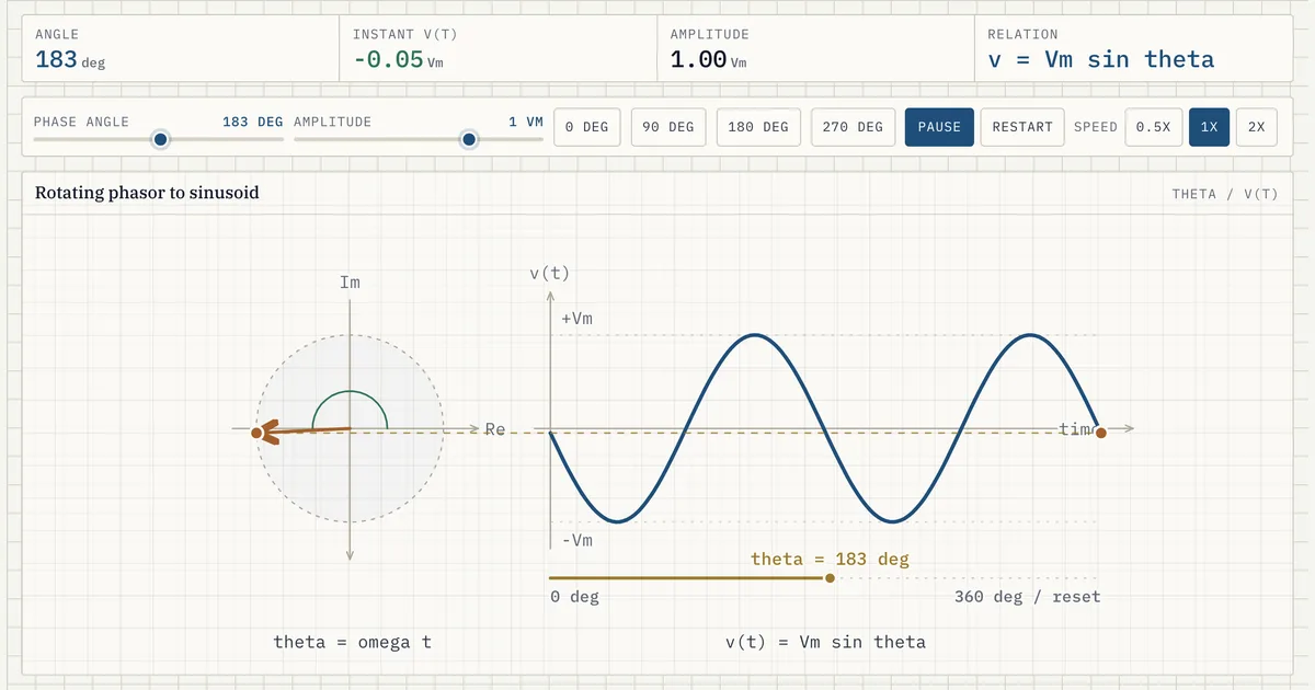
A compact view of how a rotating AC phasor maps to instantaneous sinusoidal voltage.
Download the AC Phasor and Sinusoid diagram
Free to download and reuse — including commercially — under CC BY 4.0, with credit to BESS.engineer. Licence & attribution →
Browse all BESS diagrams →
What it shows
A phasor is a rotating vector of fixed length (the amplitude Vm) spinning at the system frequency. Its vertical projection at any instant equals the instantaneous voltage, v(t) = Vm·sin(θ). As the phasor sweeps from 0° to 360°, the diagram traces out one full cycle of the AC sinusoid — the rotating picture and the time-domain wave are the same information in two views.
Why it matters for BESS
Inverters, transformers, and grid studies all reason about AC quantities as phasors. Holding amplitude and phase in your head as a single rotating vector is what makes power-factor, reactive-power, and ride-through analysis tractable — every other electrical visual in this library builds on this projection.
Frequently asked
- What is a phasor?
- A phasor is a complex number (magnitude and angle) that represents a sinusoidal quantity of known frequency. The magnitude is the waveform amplitude and the angle is its phase; rotating it and reading the vertical projection reconstructs the instantaneous value.
- Why use phasors instead of time-domain waveforms?
- At a single steady-state frequency, phasors turn differential equations into algebra. Adding two AC signals becomes vector addition, and phase relationships (leading/lagging) are read directly as angles.
- Is the phasor magnitude here the peak amplitude or the RMS value?
- Here it is the peak amplitude Vm: the phasor is drawn at full length so its vertical projection reads directly as the instantaneous voltage v(t) = Vm·sin(θ). Engineering practice and the IEEE C37.118 synchrophasor standard instead scale the magnitude to RMS, Vm/√2, so a synchrophasor is written X = (Vm/√2)·e^jφ. RMS is the convention used for power: with RMS magnitudes, complex power S = V·I* returns watts and VArs directly, with no leftover factor of ½. It is the same vector at the same angle — only the magnitude convention differs.
References
Standards and authoritative sources this visual is built on:
- IEC/IEEE 60255-118-1:2018 — Measuring relays and protection equipment — Part 118-1: Synchrophasor for power systems — Measurements (formal definition of the phasor representation of a sinusoid)
- IEEE Std 1459-2025 — IEEE Standard Definitions for the Measurement of Electric Power Quantities Under Sinusoidal, Nonsinusoidal, Balanced, or Unbalanced Conditions
- IEC 80000-6:2022 — Quantities and units — Part 6: Electromagnetism (defines instantaneous value, angular frequency, phase, and phasor quantities)