How to Read a BESS Single-Line Diagram
A BESS single-line diagram is the electrical drawing of a battery plant's power path, from the DC blocks through the PCS and the step-up transformer to the point of interconnection, drawn with standard graphic symbols and with the three AC phases collapsed onto a single line. Reading one means knowing four things: what each symbol stands for, which layers a simplified drawing has left out, what a complete drawing has to show, and which questions to put to it before it is approved.
At a glance
| Zone on the drawing | Elements that must appear | Labels that must be carried |
|---|---|---|
| DC side | Battery blocks, block and rack disconnects, DC fuses or breakers, insulation monitoring | Operating voltage window, block count, disconnect and fuse ratings |
| PCS | Converter symbol with its DC and AC sides, AC-side disconnect, output filter | Rated power, AC output voltage, declared fault-current contribution |
| LV AC bus | Busbar, incomers, any bus-section or tie point, the auxiliary tap-off | Continuous rating, short-time withstand rating and its duration |
| Step-up transformer | Two-winding symbol, winding configuration, neutral earthing arrangement | kVA rating, voltage ratio, vector group, impedance |
| MV switchgear | Circuit breakers (fixed or withdrawable), disconnects, earthing switches, surge arresters | Rated voltage, continuous current, short-time and peak withstand — plus breaking capacity for the breakers |
| Protection and metering | CTs and VTs drawn where they sit, relays by device number, lockout, revenue meter | CT and VT ratios, the class of each core, device function numbers |
| Auxiliary supply | Auxiliary transformer tap point, auxiliary board, UPS or DC control supply | Auxiliary transformer rating, normal and standby source, what each feeds |
| Point of interconnection | The ownership boundary, utility metering, the last device the plant owns | POI voltage, where the boundary falls, the revenue metering point |
A teaching one-line can leave rows out and stay useful; a drawing issued for interconnection review or construction usually cannot. The binding list comes from the interconnecting utility and the authority having jurisdiction, not from this table.
One line, three phases, and the symbols drawn on it
The word single is literal: one drawn line stands for all three phases. That is the economy of the convention — two-thirds of the conductors come off the page so topology, switching and protection stay legible. Everything else is a graphic symbol, and the two sets in circulation are not in the same state of repair. IEC 60617 is a maintained database of symbols, currently issued as IEC 60617:2026 DB, and it is what international drawings follow. IEEE Std 315-1975 was reaffirmed in 1993, then inactivated by IEEE on 7 November 2019; it is now classified Inactive-Reserved. No one maintains it, and it is still the set most North American drawings follow. The two differ in detail, so the first thing to read on any one-line is the title block naming the set it follows — and on a North American drawing, expect that to name the inactive one.
Walking outward from the battery, the recurring symbols are: parallel lines of alternating length for the battery; an open hinged blade for a disconnect; a small rectangle for a fuse; a switch closing onto a small semicircular contact for a contactor; a box split by a diagonal with DC and AC marks for the converter; two overlapping circles carrying the winding letters for a two-winding transformer; a circle sitting on the conductor for a current transformer; a miniature of that same two-circle transformer glyph, drawn off to one side of the bus, for a voltage transformer; a small box with an arrow into earth for a surge arrester. A circuit breaker is a small square in common North American practice and a switch with a cross at the contact in IEC practice — the quickest tell of which set you hold — and a withdrawable breaker carries disconnect marks either side, because racking it out is a real isolation point. Heavy lines are busbars; where one line stands for several conductors, IEC 60617 marks the count on the line itself, as one oblique stroke per conductor or as a single stroke followed by the figure.
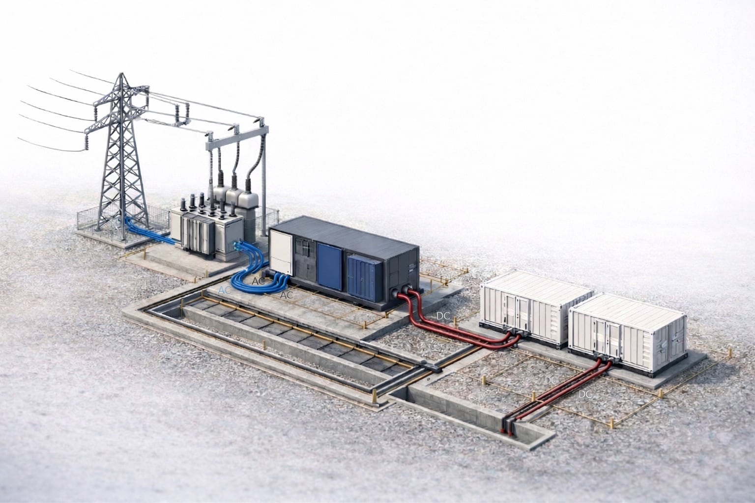
Every teaching diagram simplifies, this site included: the archetypes on the BESS single-line diagram pillar omit protection, metering, earthing and auxiliary power so the topology stays readable. The energy station model below puts the physical objects back behind the symbols — the translation you perform whenever you read a one-line.
Single-line, three-line, and the rest of the drawing set
A one-line is one document in a set, and knowing which document owns which fact settles most drawing arguments. A block diagram says what the parts are; the single-line adds bus topology, every switching device, the transformer configuration, protection and metering. The three-line diagram is the next drawing down, and it is what most requests for 'the wiring' actually mean — it draws each phase separately, so CT and VT secondary circuits, polarity marks and individual relay inputs become visible. Protection wiring is checked there, not on the one-line.
Below those sit the elementary diagrams for trip, close and interlock circuits, the wiring diagrams showing terminal-by-terminal connections, and the loop diagrams used to commission instrument circuits. Alongside them sit documents that are not drawings at all: the cable schedule for conductor sizes, the equipment list for models and ratings, the protection setting sheet for relay settings, the grounding plan for electrode detail. The one-line names devices; those documents specify them. When a reviewer asks it for a conductor size or a relay setting and the answer is not written anywhere else either, that absence is the finding.
Protection and metering: the layer teaching diagrams leave out
Protection is why the single-line exists as a review document, and it is the layer introductory drawings drop first. Functions are identified by number rather than by name, under IEEE Std C37.2-2022, the standard for electrical power system device function numbers, acronyms and contact designations. The subset that recurs on a battery plant: 50 and 51 for instantaneous and time overcurrent, 50N, 51N or 51G for earth fault, 27 and 59 for under- and overvoltage, 81U and 81O for under- and over-frequency, 87T for transformer differential, 67 for directional overcurrent, 32 for directional power, 46 for negative-sequence current, 25 for a synchronism check across a breaker that may close onto a live system, and 86 for the lockout that holds the equipment inoperative until an operator resets it, locally or remotely.
Position carries as much information as the number: overcurrent and earth-fault elements at the PCS AC terminals and on each LV incomer, differential protection wrapped around the step-up transformer between its HV and LV current transformers, voltage and frequency elements on a bus voltage transformer, directional or unbalance elements on the MV feeder. Instrument transformers must be drawn where they physically sit, because a relay only sees what its CTs enclose — a differential zone is defined by CT position and by nothing else.
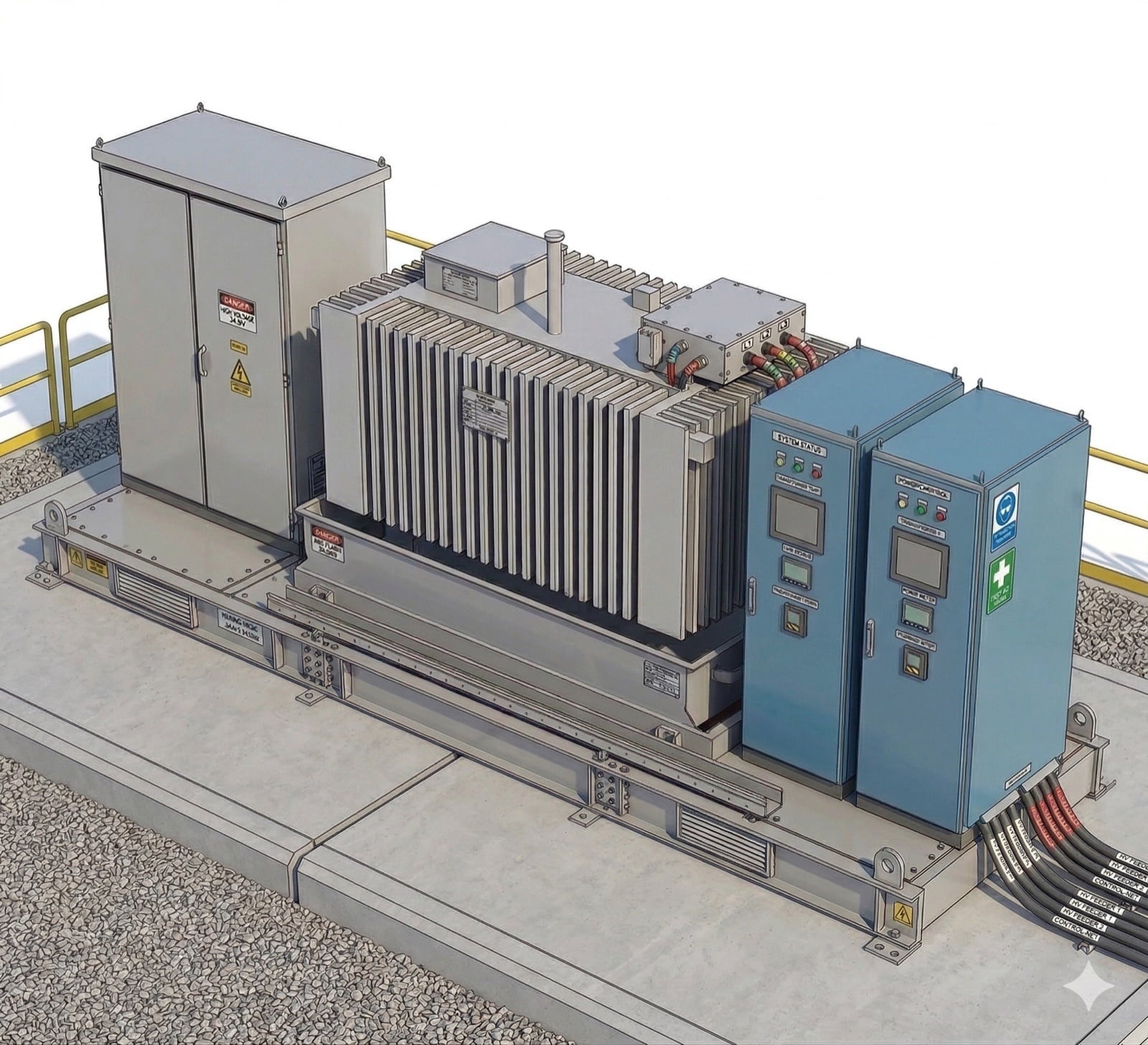
Metering runs alongside protection but is a separate chain, and the separation is between cores rather than between boxes. A protection core is specified to stay linear far above rated current so the relay still reads a fault correctly — class 5P or 10P under IEC 61869-2:2012. A metering core is specified for accuracy around rated current instead, class 0.2S or 0.5S, and is deliberately built to saturate at a few times rated current so the instruments behind it survive a fault. Revenue metering at the point of interconnection is a third measurement, commercially settled, whose accuracy class is set by the utility or the market operator rather than by the protection engineer. No single core serves all three; one current transformer routinely does, because a single unit carries several independent secondary cores wound on the same primary, and a 0.2S metering core alongside one or two 5P protection cores is the ordinary way an IEC 62271-200 metal-enclosed switchgear panel is specified. So read the ratio and the class written against each core, not against the CT. The MV skid model below shows the switchgear cabinet this layer is packed into; the cores and relays themselves sit inside it, off the model.
Earthing and the winding configuration decide how faults appear
The transformer symbol carries more design decision than any other mark. Its winding configuration is a connection symbol in the IEC 60076-1:2011 notation: upper case for the high-voltage winding and lower case for the low-voltage one, D or d for delta, Y or y for star (wye), n when the star point is brought out as an accessible neutral, and a number for the phase displacement — a clock position, each hour being 30 degrees. Dyn11 therefore reads as a delta high-voltage winding, a star low-voltage winding with its neutral available, and a low-voltage phasor leading by 30 degrees.
How that neutral is treated is a separate decision and must be shown separately. A solidly earthed star point gives a large earth-fault current that overcurrent protection detects easily; a neutral earthing resistor limits it to a chosen, still-detectable value; a high-resistance-earthed or unearthed system limits it further and can run through a first earth fault, at the cost of a scheme to locate it. It is rarely a free choice — an interconnection agreement may require the plant to present an effectively earthed source at the point of interconnection, so vector group and neutral treatment are usually settled in the interconnection study rather than by the EPC.
The DC side runs the other way. Battery blocks are commonly operated unearthed, neither pole bonded, so a first pole-to-earth fault has no low-impedance return path. Current still flows: a brief capacitive discharge into the distributed line-to-earth capacitance, and then a steady current set by the insulation resistance of the opposite pole in series with the measuring resistance of the monitoring device — real current, orders of magnitude below anything an overcurrent device is set to see. That is precisely the problem. The fault silently removes one of two insulation barriers and the plant keeps running, which is why the DC bus carries an insulation-monitoring device that reads insulation resistance rather than an earth-fault relay that reads current, and why a DC earth alarm is normally an operational event rather than a trip. Something comparable happens on a three-wire AC system: with the line currents forced to sum to zero, imbalance reappears as a shift of the neutral point and an overvoltage on the lightly loaded phases, which the floating-neutral visual below shows directly.
The auxiliary supply, and where it branches
Station service is the branch teaching one-lines omit and the one most often redrawn. A BESS consumes power while doing nothing commercial: thermal management, fire detection and suppression, controls and communications, lighting, and the energy to trip and close switchgear. The auxiliary load estimator sizes the demand; the drawing has to say where it is fed from.
There are two topologies and they are not equivalent. An auxiliary transformer tapped off the plant’s own medium-voltage collection is cheap and simple but dies with the collection system, so a plant that loses its MV supply loses the cooling and controls that hold the batteries in a safe state. A separate utility service, sized only for the auxiliary load, keeps the site alive while the plant is out. Many plants have both, and the one-line must show which source is normal, which is standby, and where the transfer happens.
Below the auxiliary board sits a quieter layer: protection relays, breaker trip and close coils, and the controls that force a defined safe state are fed from a battery-backed DC system or a UPS, so that losing all AC does not also remove the ability to trip. A one-line that draws relays but no supply to them has not finished. Trace what stays energised when the incoming supply is dead.
AC-coupled or DC-coupled: where a hybrid splits on the one line
For a solar-plus-storage or wind-plus-storage plant, the most consequential thing a one-line tells you is where the two resources meet. In an AC-coupled hybrid they meet after conversion: the PV inverters and the battery PCS are separate conversion blocks with their own step-up transformers, paralleled on the medium-voltage collection or at the main power transformer, each able to be studied, protected and metered largely on its own.
In a DC-coupled hybrid they meet before conversion. The battery sits on the same DC bus as the PV array, behind a DC-DC converter, sharing one inverter and one step-up transformer, so a whole conversion chain leaves the drawing and a DC-DC stage joins it. The protection problem changes with it: the shared inverter now has two sources behind it, and the export limit is enforced on their sum rather than block by block. Either way that limit and the interconnection obligations belong to the point of interconnection rather than to any block, which is why a hybrid one-line must make the boundary explicit and show the metering that proves compliance with it. The coupling visual below flips between the two topologies as single-line drawings.
What an EPC or owner should check before signing
Start with the title block, because status decides what the content means. Issued for review invites comment; issued for construction is what people build from; as-built is what actually exists, and the distance between the last two is where commissioning surprises live. Read the revision number and date, the change note, and who drew, checked and approved it — and where a jurisdiction requires a professional engineer to seal interconnection or permit drawings, confirm the version being approved is the sealed one.
Then read it as a device chain rather than a picture. Every switching device should carry a rating, and every interrupting device — circuit breaker, switch-disconnector, fuse — a breaking capacity as well, per IEC 62271-100:2021 on the MV side. Do not ask a disconnector or an earthing switch for one. Under IEC 62271-102:2018 they are rated for short-time withstand current and its duration and for peak withstand current, and the earthing switch additionally for short-circuit making capacity; a disconnector is not rated to break load current at all, which is the whole reason the drawing carries interlocks around it. A reviewer who raises a finding against every isolator for a missing breaking capacity has misread the device. Every transformer needs a kVA rating, ratio, vector group and impedance; every protection element a device number and instrument transformers that genuinely enclose what it protects. Confirm the earthing arrangement is drawn and matches what the interconnection study assumed, that the auxiliary and DC control supplies both appear, and that the point of interconnection is marked as an ownership boundary rather than left implied. Where the one-line disagrees with the equipment list, the cable schedule or the setting sheet, the disagreement is the finding: one of them is wrong.
Finally, keep in view what the drawing feeds. The one-line is the input to load-flow, short-circuit and arc-flash studies, to protection coordination, and to the equipment duty ratings those studies produce, each of which reads topology, impedances and device positions straight off it. An error propagates into a study, then a relay setting, then a device that fails to operate when it is needed — the argument for an independent read of the one-line before approval rather than after.
Frequently asked
- How do you read a single-line diagram?
- Read it as a chain from one end to the other, remembering that the single drawn line represents all three phases at once. On a BESS, start at the battery blocks and follow the line through every device in order: disconnects and fuses, the converter, the low-voltage bus, the step-up transformer, the medium-voltage switchgear, and the point of interconnection. At each device read three things — the symbol (what it is), the label beside it (how it is rated), and its position relative to the current transformers around it (what protection can see it). The title block says which symbol standard the drawing follows and what revision state it is in.
- What is the difference between a single-line diagram and a three-line diagram?
- A single-line diagram represents all three phases with one line, so it shows topology, switching and protection without the clutter of individual conductors. A three-line diagram draws each phase separately, which is what makes current-transformer and voltage-transformer secondary circuits, polarity marks and individual relay inputs visible. The single-line is the document used for interconnection review and system studies; the three-line is the document used to wire and commission protection. A project normally needs both, and a request for the wiring diagram is usually a request for the three-line.
- What are the ANSI device numbers on a BESS single-line diagram?
- They are device function identifiers defined by IEEE Std C37.2-2022, the standard for electrical power system device function numbers, acronyms and contact designations. It assigns 95 numbers and 22 acronyms to devices and functions generally, not only to protective ones — 86 in the list below is an auxiliary lockout rather than a protection element. The ones that recur on a battery plant one-line are 50 and 51 (instantaneous and time overcurrent), 50N, 51N or 51G (earth fault), 27 and 59 (under- and overvoltage), 81U and 81O (under- and over-frequency), 87T (transformer differential), 67 (directional overcurrent), 32 (directional power), 46 (negative-sequence current), 25 (synchronism check) and 86 (lockout). The number gives the function; where it is drawn gives what it protects, because a relay only sees what its instrument transformers enclose.
- What does Dyn11 mean on a BESS transformer?
- It is a winding connection symbol in the IEC 60076-1:2011 notation. The capital letter describes the high-voltage winding and the lower-case letter the low-voltage one: D is delta, y is star (wye), and n means the star point is brought out as an accessible neutral. The number is a clock position for the phase displacement between the windings, each hour being 30 degrees, so 11 means the low-voltage phasor leads the high-voltage one by 30 degrees. It matters because the configuration decides how an earth fault on one side appears on the other, and therefore what protection can detect.
- Where does auxiliary power come from on a BESS single-line diagram?
- From one of two places, and the drawing has to say which. An auxiliary transformer can be tapped off the plant’s own medium-voltage collection, which is simple but leaves the site without cooling, controls or communications whenever the collection system is out; or a separate utility service can feed the auxiliary board independently. Many plants have both, with a transfer arrangement between them that the one-line should show. Below the auxiliary board there is normally a battery-backed DC supply or a UPS for protection relays and breaker trip coils, so the plant can still be tripped with no AC present.
- What is the difference between an AC-coupled and a DC-coupled hybrid on a single-line diagram?
- The coupling point. An AC-coupled solar-plus-storage plant is drawn as two complete conversion chains — PV inverters with their transformer, battery PCS with its transformer — meeting on the AC collection system. A DC-coupled plant puts the battery on the same DC bus as the PV array behind a DC-DC converter, sharing one inverter and one step-up transformer, so a whole conversion chain leaves the drawing and a DC-DC stage joins it. In both cases the export limit is enforced at the point of interconnection, which is why that boundary and its metering have to be explicit.
- What should an owner check on a BESS single-line diagram before approving it?
- Check the title block first: revision number, date, status (issued for review, issued for construction, or as-built), who drew, checked and approved it, and whether a professional seal is required and present. Then confirm that every switching device carries a rating and every interrupting device a breaking capacity as well — a disconnector or earthing switch will not, because IEC 62271-102:2018 rates them for short-time and peak withstand current, and the earthing switch for short-circuit making capacity, rather than for breaking anything. Confirm that the transformer shows kVA, ratio, vector group and impedance, that protection elements carry device numbers and sit inside instrument transformers that actually enclose what they protect, and that the earthing arrangement, the auxiliary and DC control supplies, and the point of interconnection as an ownership boundary are all drawn. Any disagreement with the equipment list, cable schedule or setting sheet is itself a finding.
References
Standards this guide is written from (first 7), followed by the sources carried by the interactive visuals embedded above:
- IEC 60617 — Graphical symbols for diagrams
- IEEE Std 315-1975 (R1993) — Graphic Symbols for Electrical and Electronics Diagrams (Including Reference Designation Letters)
- IEEE Std C37.2-2022 — Electrical Power System Device Function Numbers, Acronyms, and Contact Designations
- IEC 60076-1:2011 — Power transformers, Part 1: General
- IEC 61869-2:2012 — Instrument transformers, Part 2: Additional requirements for current transformers
- IEC 62271-102:2018 — High-voltage switchgear and controlgear, Part 102: Alternating current disconnectors and earthing switches
- IEC 62271-100:2021 — High-voltage switchgear and controlgear, Part 100: Alternating-current circuit-breakers
- IEEE 2800-2022 — Standard for Interconnection and Interoperability of Inverter-Based Resources (IBRs) Interconnecting with Associated Transmission Electric Power Systems
- IEEE 1547-2018 — Standard for Interconnection and Interoperability of Distributed Energy Resources with Associated Electric Power Systems Interfaces
- IEC 62933-1 — Electrical Energy Storage (EES) Systems — Part 1: Terminology (Vocabulary)
- Grid-Scale Battery Storage: Frequently Asked Questions (NREL/TP-6A20-74426)
- UL 1741 — Inverters, Converters, Controllers and Interconnection System Equipment for Use With Distributed Energy Resources
- IEEE Std C57.12.00 — Standard for General Requirements for Liquid-Immersed Distribution, Power, and Regulating Transformers
- IEC 62271-200 — High-voltage switchgear and controlgear – Part 200: AC metal-enclosed switchgear and controlgear for rated voltages above 1 kV and up to and including 52 kV
- IEEE Std 142 (Green Book) — IEEE Recommended Practice for Grounding of Industrial and Commercial Power Systems
- IEEE Std C62.92.1 — IEEE Guide for the Application of Neutral Grounding in Electrical Utility Systems, Part I: Introduction
- IEEE Std 141 (Red Book) — IEEE Recommended Practice for Electric Power Distribution for Industrial Plants