BESS Container Controls
The container control layer that keeps battery racks inside safe operating limits.
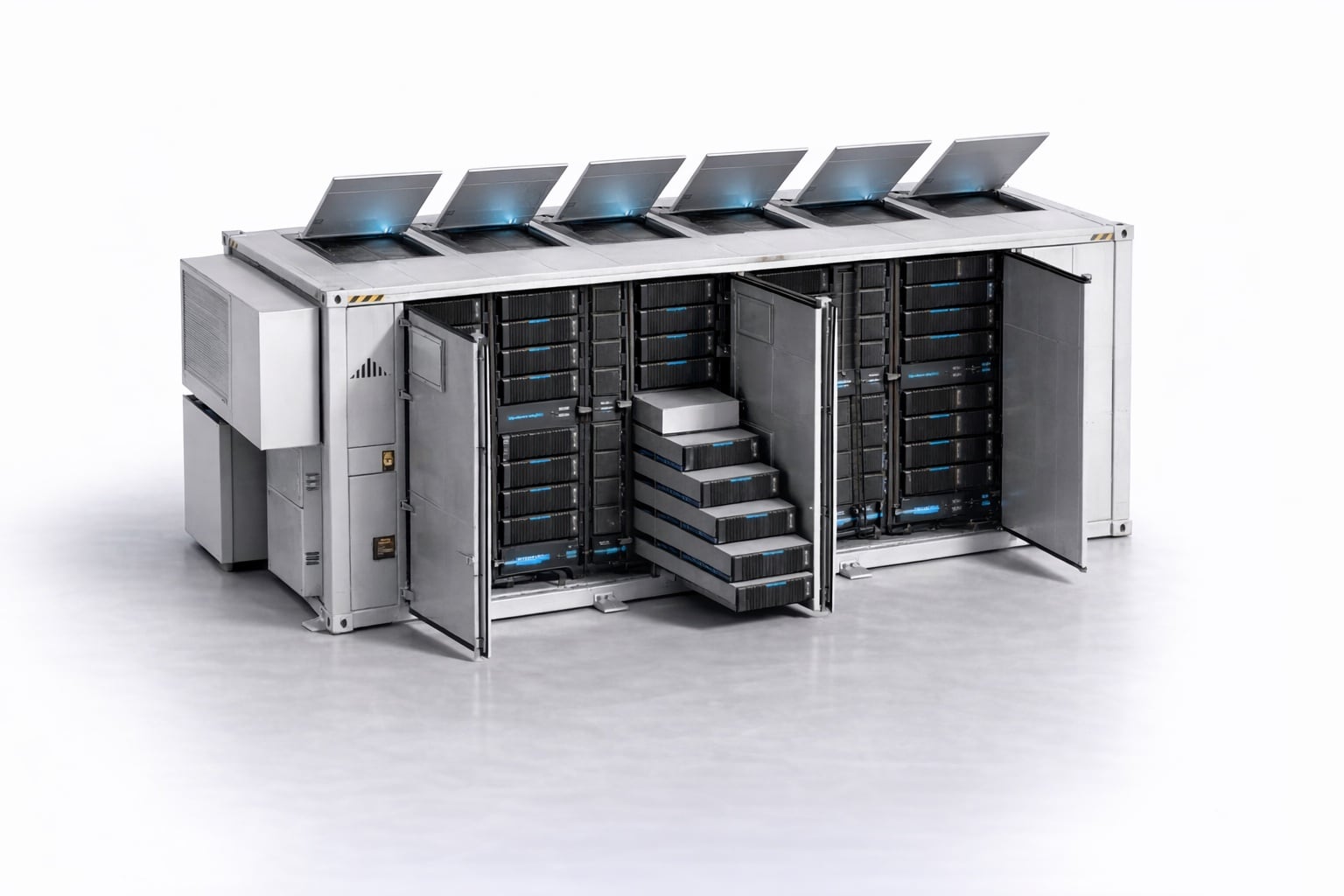
Download the BESS Container Controls diagram
Free to download and reuse — including commercially — under CC BY 4.0, with credit to BESS.engineer. Licence & attribution →
Browse all BESS diagrams →
What it shows
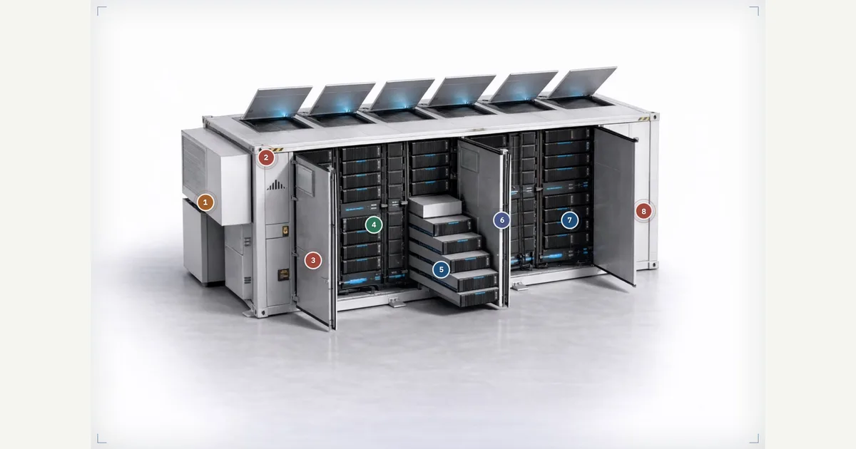
The container control layer is the set of sensing, BMS, thermal, and safety systems that keep battery racks inside safe operating limits. This annotated container photo places eight markers grouped into five signal categories: Cell & Module Sensing, BMS Control, Thermal Control, Safety Signals, and Comms & Data. Hover or tap any marker to inspect one link in the chain — from module voltage and temperature up to the container BMS and the emergency stop circuit.
Why it matters for BESS
A battery container is only as safe as the signals that govern it. Control here is hierarchical: module sensing feeds the rack BMS, rack data aggregates into the container BMS, and that container layer produces the usable current and voltage limits the PCS and plant controller must respect. Alongside it, HVAC holds cell temperature, fire and gas detection triggers shutdown, and access interlocks plus the E-stop chain force a defined safe state — the difference between a controlled trip and thermal runaway.
How to read it
Follow the chain by category. Sensing (green) reports module voltage and temperature. BMS Control (primary) shows the rack controller managing contactors and reporting availability, then the container BMS combining rack data into limits and status. Thermal (accent) is HVAC command and feedback. Safety (warning) covers fire and gas detection, door interlocks, and the emergency stop chain. Comms & Data carries all of it — Modbus, CAN, Ethernet — toward SCADA and the plant controller.
Frequently asked
- What is the difference between a rack BMS and a container BMS?
- The rack BMS is hardware that aggregates module-level data, manages contactor logic, and reports each rack's availability. The container BMS sits one level up, combining data from all racks into usable current and voltage limits, alarms, and status points. Those container-level limits are what the PCS and plant controller actually respect during operation.
- What safety signals does a BESS container controller monitor?
- Three main groups. Fire and gas detection senses smoke, heat, or abnormal gas and triggers alarms, shutdown, ventilation, or suppression. Door and access interlocks enforce safe maintenance states during service. The emergency stop chain forces the container into a defined safe state and communicates that trip upward to plant controls. Together they take priority over normal dispatch.
- How does module sensing connect to the rest of the control chain?
- Module-level sensing reports voltage, temperature, and status so the rack BMS can balance operation, identify faults, and constrain current. That rack data is then passed up to the container BMS, which turns it into the operating limits the PCS must stay within. The hierarchy runs cell to module to rack to container, and only the container layer talks to the plant.
- What role does HVAC play in the container control layer?
- HVAC regulates container temperature to keep cells inside their safe operating window, and reports alarms, run status, and availability back to the container controller. It is a thermal control function, distinct from the fire and gas detection safety system — HVAC manages normal temperature, while detection responds to abnormal or emergency conditions.
References
Standards and authoritative sources this visual is built on:
- IEC 62933-5-2: Electrical energy storage (EES) systems — Part 5-2: Safety requirements for grid-integrated EES systems — Electrochemical-based systems
- NFPA 855: Standard for the Installation of Stationary Energy Storage Systems
- UL 9540: Standard for Energy Storage Systems and Equipment
- UL 1973: Standard for Batteries for Use in Stationary and Motive Auxiliary Power Applications