Voltage Ride-Through
Ride-through depends on voltage, current, thermal stress, and timer coordination.
Part of: the grid-code ride-through chart — compare LVRT, HVRT and FRT envelopes across 64 grid codes, 50 verified on every curve.
Download the Voltage Ride-Through diagram
Free to download and reuse — including commercially — under CC BY 4.0, with credit to BESS.engineer. Licence & attribution →
Browse all BESS diagrams →
What it shows
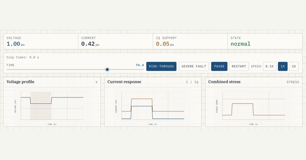
Voltage ride-through is a grid-code requirement that a battery inverter stay connected and inject reactive current through a voltage sag rather than disconnecting. The demo traces an 8-second fault event across three synchronized charts: voltage in per-unit, current and reactive current (Iq) in per-unit, and a combined stress index. Two selectable scenarios, a survivable ride-through and a severe fault, show why one is ridden through and the other trips.
Why it matters for BESS
During a grid fault, mass disconnection of inverter-based resources can turn a local sag into a wider outage, so grid codes require batteries to ride through and actively support voltage with reactive current. But an inverter's semiconductors have a finite current and thermal limit. Ride-through is therefore a coordination problem: hold on and inject Iq to help the grid recover, but trip before accumulated stress damages the hardware. This visual makes that trade-off concrete.
How to read it
The fault begins at t=1.2s. In the ride-through scenario voltage dips to 0.72 pu, current rises to 1.05 pu, Iq injection reaches 0.68 pu, and the stress index sits at 0.78, below the limit line at 1.0, so the unit survives until the fault clears near 3.9s. In the severe-fault scenario voltage collapses to 0.28 pu, current hits 1.24 pu, stress crosses 1.0, and the trip timer runs out at t=3.2s, disconnecting the unit.
Frequently asked
- What is voltage ride-through (LVRT)?
- Low-voltage ride-through is a grid-code obligation for a battery inverter to remain connected through a voltage sag instead of tripping offline. During the sag the inverter also injects reactive current to help pull voltage back up. It only disconnects if the sag is deep and long enough that riding through would exceed the hardware's current and thermal limits.
- Why does a deeper voltage sag cause a trip when a shallower one does not?
- A deeper sag demands more current to deliver the same support, and current drives thermal stress in the inverter's switches. In the demo the shallow sag holds voltage at 0.72 pu with a stress index of 0.78, safely under the limit, while the deep sag drops to 0.28 pu, pushes current to 1.24 pu, and drives stress above 1.0. Once that accumulated stress and the trip timer coincide, the unit disconnects to protect itself.
- What is reactive current (Iq) injection during a fault?
- Iq is the reactive component of the inverter's output current, injected specifically to raise voltage at the point of connection during a sag. The deeper the sag, the more Iq grid codes require: the demo shows Iq climbing from about 0.05 pu in normal operation to 0.68 pu in the ride-through case and 0.95 pu in the severe fault. It is voltage support, not active power delivery.
- How does the trip timer decide ride-through versus disconnect?
- The trip timer coordinates how long the inverter tolerates a given sag depth before disconnecting, mirroring a grid code's voltage-versus-time ride-through envelope. A shallow sag has effectively unlimited hold time, so the timer never expires. In the severe-fault scenario the timer accumulates from the fault onset at 1.2s and reaches its limit at 3.2s, at which point the unit trips and current falls to zero.
- What is high-voltage ride-through (HVRT), and how does it differ from LVRT?
- High-voltage ride-through is the mirror image of LVRT: when grid voltage rises above the roughly 0.9 to 1.1 pu continuous band, the inverter must stay connected but now absorbs reactive current instead of injecting it, pulling the swell back down rather than propping voltage up. The envelope is still voltage-versus-time, but it tightens as voltage climbs — a modest overvoltage can be held for seconds, while near 1.2 pu IEEE 2800 requires only about a second of ride-through before a trip is permitted. Grid codes like IEEE 2800 specify both halves of the curve so a swell, like a sag, does not cause mass disconnection of inverter-based resources. The standard also restricts momentary cessation, so the inverter is expected to keep regulating current through the event rather than briefly blocking output.
References
Standards and authoritative sources this visual is built on:
- IEEE 2800-2022 — IEEE Standard for Interconnection and Interoperability of Inverter-Based Resources (IBRs) Interconnecting with Associated Transmission Electric Power Systems (voltage ride-through and dynamic reactive current injection requirements)
- IEEE 1547-2018 — IEEE Standard for Interconnection and Interoperability of Distributed Energy Resources with Associated Electric Power Systems Interfaces (voltage ride-through Categories I/II/III and trip/ride-through envelopes)
- NERC Reliability Standard PRC-024-3 — Frequency and Voltage Protection Settings for Generating Resources (voltage ride-through no-trip curves)
- Commission Regulation (EU) 2016/631 — Network Code on Requirements for Generators (RfG): fault-ride-through and fast fault-current (reactive current) requirements
- Odessa Disturbance — Texas Event May 9, 2021 (joint NERC / Texas RE report on inverter-based-resource mass tripping)