PCS Control Loop
How the PCS turns plant commands into grid-synchronized power conversion.
Download the PCS Control Loop diagram
Free to download and reuse — including commercially — under CC BY 4.0, with credit to BESS.engineer. Licence & attribution →
Browse all BESS diagrams →
What it shows
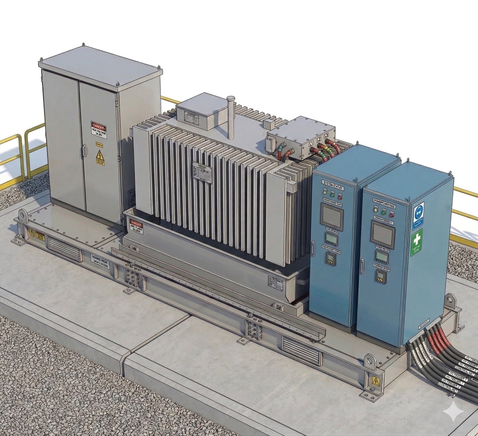
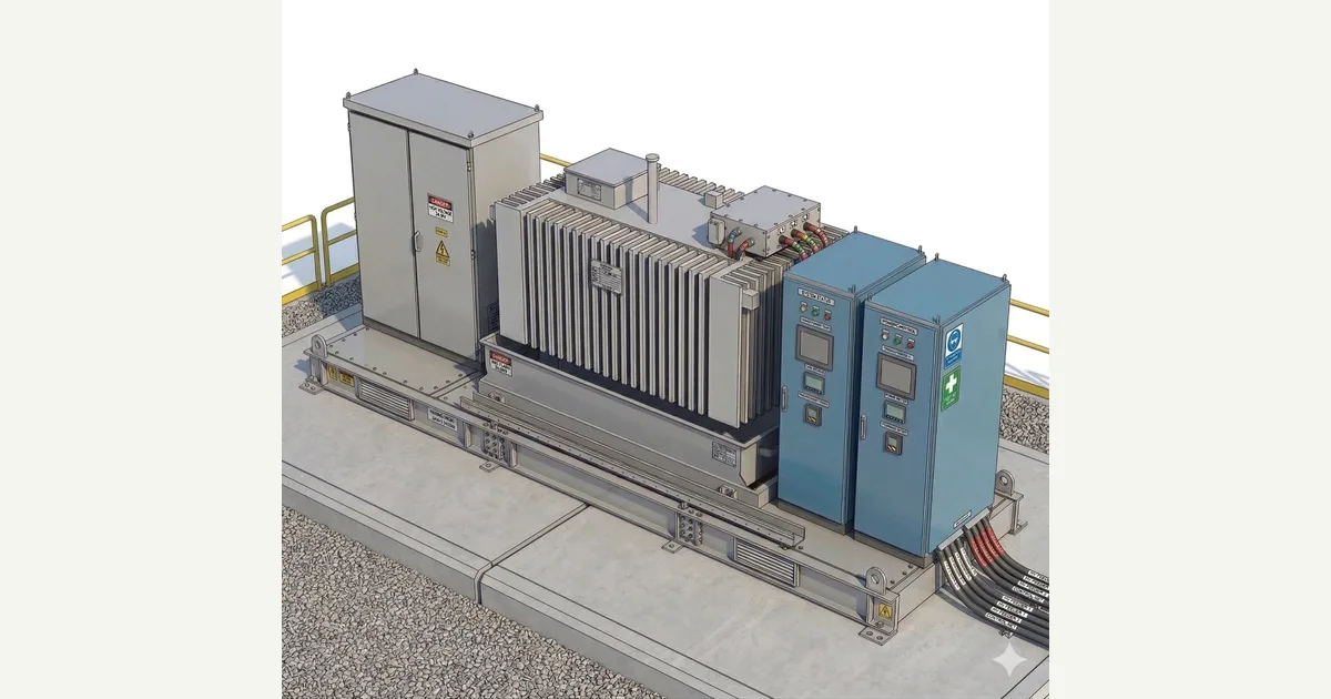
The PCS control loop is the command-and-feedback chain that turns a plant-level power request into grid-synchronized AC. On a photo of a PCS and MV transformer skid, eight markers trace the path: the PPC's active/reactive power reference enters, the inverter controller converts it into switching behavior, and protection, telemetry, and auxiliary signals feed back. Markers are colour-coded by role - reference command, inverter control, protection, telemetry feedback, and auxiliary control.
Why it matters for BESS
A grid-scale battery only delivers what the control hierarchy commands, and each layer has a distinct scope. The PPC decides plant-wide P and Q and ramp rate; the PCS inverter controller executes it while holding grid-code functions, current limits, and synchronization; MV protection and DC-interface signals constrain what conversion is allowed. Confusing these boundaries - expecting the inverter to set plant targets, or protection to shape power quality - is where real dispatch and fault-response problems begin.
How to read it
Follow the loop clockwise. Marker 1 (PPC P/Q reference) is the input; marker 5 (inverter controller) turns it into PWM switching and grid-code behavior; marker 7 (DC cable interface) reports the battery-bus voltage, current, and isolation that limit conversion. The feedback half - transformer temperature, MV protection relay, and power-quality measurements (P, Q, voltage, frequency, harmonics) - returns to the PPC so it can correct the next command. Auxiliary and HMI markers cover cabinet, ventilation, and service state.
Frequently asked
- What is a PCS control loop?
- It is the closed command-and-feedback chain between the power plant controller (PPC) and the power conversion system (PCS). The PPC issues active and reactive power references; the PCS inverter controller converts them into grid-synchronized switching; and telemetry, protection, and DC-interface signals feed measurements back so the PPC can correct the next command. The loop is what keeps delivered power tracking the plant target.
- What is the difference between the PPC and the PCS inverter controller?
- The PPC is the plant-level brain: it sets the site-wide active power (P), reactive power (Q), and ramp-rate targets at the grid interface. The PCS inverter controller is the executor: it turns those references into PWM switching while managing synchronization, current limits, and grid-code functions for its own unit. The PPC decides what the plant should produce; the inverter controller decides how one PCS achieves its share.
- What feedback signals close the PCS control loop?
- Three kinds. Telemetry reports power, reactive power, voltage, frequency, harmonics, and alarms back to the PPC. Protection relays report abnormal voltage, current, frequency, or fault conditions and coordinate trips. The DC cable interface reports battery-bus voltage, current, and isolation status. Transformer temperature and auxiliary signals add derating and service context. Together they let the PPC verify what was actually delivered.
- Why does the DC interface constrain the inverter's output?
- The PCS converts between the DC battery bus and the AC grid, so its AC output is bounded by what the DC side can supply or absorb. The DC cable interface reports DC voltage, current, and isolation status; low DC voltage, a current limit, or an isolation fault directly restricts or halts conversion, regardless of the P/Q reference the PPC is sending. AC and DC ratings are distinct, and the DC condition wins.
References
Standards and authoritative sources this visual is built on:
- IEEE 2800-2022 — IEEE Standard for Interconnection and Interoperability of Inverter-Based Resources (IBRs) Interconnecting with Associated Transmission Electric Power Systems
- IEEE 1547-2018 — IEEE Standard for Interconnection and Interoperability of Distributed Energy Resources with Associated Electric Power Systems Interfaces
- IEEE 519-2022 — IEEE Standard for Harmonic Control in Electric Power Systems
- Reliability Guideline: BPS-Connected Inverter-Based Resource Performance