Grid Support Functions
How active and reactive support curves respond to frequency and voltage deviations.
Part of: the grid-code ride-through chart — the voltage and frequency envelopes these functions are judged against.
Download the Grid Support Functions diagram
Free to download and reuse — including commercially — under CC BY 4.0, with credit to BESS.engineer. Licence & attribution →
Browse all BESS diagrams →
What it shows
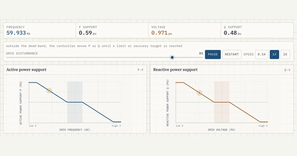
Grid support functions are the automatic control laws that make a battery adjust its active and reactive power in response to grid frequency and voltage. This visual shows two response curves side by side: a P-f curve where active-power support ramps up once frequency leaves the 59.98-60.02 Hz dead-band, and a Q-V curve where reactive support engages outside a 0.99-1.01 pu voltage band. One slider sweeps a grid disturbance across both.
Why it matters for BESS
Grid codes require inverter-based resources to help hold frequency and voltage, and these two functions are how a battery delivers that. The P-f function is active power (MW) responding to frequency: it discharges when the grid slows and absorbs when it speeds up. The Q-V function is reactive power (MVAr) responding to voltage, injecting Q when voltage sags and absorbing it when voltage rises. Because they act on independent quantities, P and Q are commanded separately within the converter's S = sqrt(P^2 + Q^2) envelope.
How to read it
Drag the grid-disturbance slider, or press play to auto-sweep. Watch the operating-point dot travel along each curve. Inside the shaded dead-band the support stays flat at zero pu — the controller ignores small deviations. Cross 59.98 or 60.02 Hz and active-power support climbs linearly to full ±1 pu over the next 0.08 Hz (a slope compressed for legibility — real droop reaches full output over roughly 0.5-3 Hz); the Q-V curve behaves the same way outside 0.99-1.01 pu. The readouts report frequency, voltage, and the resulting P and Q support in per-unit.
Frequently asked
- What are grid support functions in a battery energy storage system?
- They are automatic control functions that adjust the inverter's output to help stabilise the grid. The two main ones are active-power-frequency (P-f) support, which changes real power in response to frequency, and reactive-power-voltage (Q-V) support, which changes reactive power in response to voltage. They run continuously in the PCS controls and only act once the deviation exceeds a set dead-band.
- What is a dead-band in a P-f or Q-V response curve?
- A dead-band is a range around nominal where the controller deliberately does nothing, so it doesn't chase normal grid noise. In this visual the frequency dead-band is 59.98-60.02 Hz (±0.02 Hz around 60 Hz) and the voltage dead-band is 0.99-1.01 pu (±0.01 pu). Support only ramps up once the disturbance moves outside these limits.
- Does a battery inject active or reactive power for a low-voltage event?
- Reactive power. Voltage is supported by the Q-V function, so a voltage sag below 0.99 pu commands the converter to inject reactive power (MVAr) to raise it. Active power (MW) is reserved for the P-f function, which reacts to frequency, not voltage — the two loops act on separate quantities.
- Why does the support curve flatten out at the edges?
- Because the support saturates at the converter's limit, shown here as ±1 pu. Active-power support rises linearly to full output beyond the dead-band (here over 0.08 Hz, compressed for legibility; real droop spans ~0.5-3 Hz), then holds flat — the battery cannot deliver more than its rating. The same applies to the Q-V curve within the PCS reactive-power capability.
References
Standards and authoritative sources this visual is built on:
- IEEE Std 2800-2022 — IEEE Standard for Interconnection and Interoperability of Inverter-Based Resources (IBRs) Interconnecting with Associated Transmission Electric Power Systems
- IEEE Std 1547-2018 — IEEE Standard for Interconnection and Interoperability of Distributed Energy Resources with Associated Electric Power Systems Interfaces (frequency-droop and voltage-reactive power functions with dead-bands)
- Reliability Guideline: BPS-Connected Inverter-Based Resource Performance (frequency and voltage support requirements for inverter-based resources)