Grid Inertia and RoCoF
How aggregate inertia shapes frequency slope, nadir, and load-shedding margin after a contingency.
Part of: the grid-code ride-through chart — the frequency envelopes a plant must ride through when inertia is low.
Download the Grid Inertia and RoCoF diagram
Free to download and reuse — including commercially — under CC BY 4.0, with credit to BESS.engineer. Licence & attribution →
Browse all BESS diagrams →
What it shows
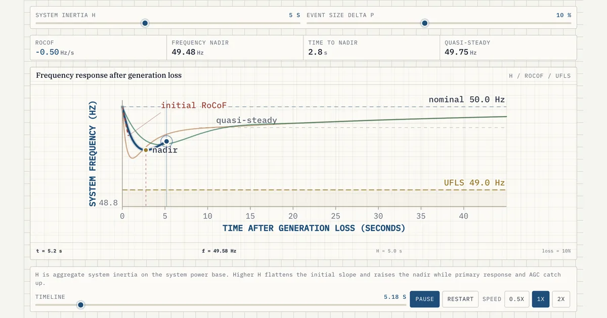
When generation is suddenly lost, frequency falls. The initial slope — the rate of change of frequency (RoCoF) — is set by how much rotational inertia the system has. Lower inertia means a steeper initial drop and a deeper nadir, risking under-frequency load shedding (UFLS). The curve shows how inertia and fast response together determine whether frequency recovers before the UFLS threshold is crossed.
Why it matters for BESS
Inverter-based resources do not inherently provide inertia, but a BESS can deliver fast frequency response within milliseconds — arresting the decline and raising the nadir — and, as a grid-forming resource providing synthetic inertia, can also blunt the initial RoCoF that system inertia otherwise sets. This is one of the highest-value grid services storage provides as conventional inertia declines.
How to read it
Follow the trace left to right: the initial slope out of 50.0 Hz is the RoCoF — steeper means less inertia. The lowest point of the dip is the nadir; if it touches the dashed 49.0 Hz line, under-frequency load shedding trips. The slow climb after the nadir is the primary response pulling frequency back toward a quasi-steady value below nominal. Move the sliders and watch which of the three features each one changes.
Frequently asked
- What is RoCoF?
- RoCoF is the rate of change of frequency (Hz/s) immediately after a power imbalance. It is inversely proportional to system inertia: less inertia gives a faster, more dangerous frequency excursion.
- Can battery storage provide inertia?
- Not true mechanical inertia, but grid-forming and fast-response BESS can emulate it (synthetic inertia) and deliver fast frequency response far quicker than governors on conventional plant, which arrests the frequency decline.
- What is UFLS and why does the chart mark 49.0 Hz?
- Under-frequency load shedding is the grid's last automatic defence: relays disconnect blocks of load in stages to arrest a falling frequency. On a 50 Hz system the first stages typically sit near 49.0 Hz, so the chart marks it as the line the nadir must not cross. Exact stages and settings vary by grid code.
- How does BESS fast frequency response change the nadir?
- Injecting active power within the first few hundred milliseconds replaces part of the lost generation while frequency is still falling, arresting the fall and raising the nadir. The initial RoCoF itself is set by system inertia (RoCoF = f0·ΔP/2H) before any resource can act; genuine synthetic inertia — responding to the rate of change of frequency — is what reduces that initial slope. The earlier the response lands, the more each megawatt is worth — which is why services like ERCOT FFR require full delivery within about 0.25 s.
References
Standards and authoritative sources this visual is built on:
- IEEE Std 2800-2022 — IEEE Standard for Interconnection and Interoperability of Inverter-Based Resources (IBRs) Interconnecting with Associated Transmission Electric Power Systems (frequency response, RoCoF ride-through, and fast frequency response requirements)
- Fast Frequency Response Concepts and Bulk Power System Reliability Needs
- Inertia and the Power Grid: A Guide Without the Spin (NREL/TP-6A20-73856)
- Rate of Change of Frequency (RoCoF) withstand capability — ENTSO-E guidance note for the network code on requirements for grid connection
- ERCOT Nodal Protocols — Responsive Reserve Service and the Fast Frequency Response (FFR) component (0.25 s deployment requirement)