GFM Current Saturation
Why a small voltage step can demand too much current in a strong grid.
Download the GFM Current Saturation diagram
Free to download and reuse — including commercially — under CC BY 4.0, with credit to BESS.engineer. Licence & attribution →
Browse all BESS diagrams →
What it shows
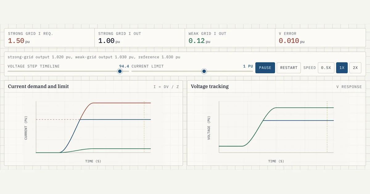
GFM current saturation is what happens when a grid-forming inverter's commanded current hits its limit before it can drive grid voltage to reference. This demo animates a voltage step (up to 0.03 pu) through Ohm's law, I = dV/Z: in a strong grid (Z about 0.02 pu) the request reaches roughly 1.5 pu and clips at the current limit, while in a weaker grid (Z about 0.25 pu) the same step asks only about 0.12 pu and tracks cleanly.
Why it matters for BESS
Grid-forming BESS inverters act as a controlled voltage source behind a coupling impedance, but their current is hard-limited by the PCS and IGBT ratings, typically around 1.1 to 1.2 pu. On a strong, low-impedance grid the coupling term is tiny, so even a modest voltage error demands current far beyond that ceiling, forcing the controller to clip. The counterintuitive result is that a strong grid saturates current sooner than a weak one, which drives PCS overcurrent headroom and control-tuning decisions.
How to read it
The left chart plots current (pu) over a 5-second timeline: the warning trace is the raw strong-grid request, the primary trace is the limited output, and the horizontal primary line is the current limit you set with the slider (0.7 to 1.2 pu). The green trace is the weak grid, which stays well under the limit. The right chart shows voltage tracking, with the accent dashed line as the reference; when the strong-grid output clips it falls short, and the V error readout turns to warning tone above 0.008 pu.
Frequently asked
- What is current saturation in a grid-forming inverter?
- Current saturation is when a grid-forming inverter's commanded current exceeds its hardware limit and gets clipped, so the output current stops rising even though the control loop is still asking for more. Because the inverter can no longer inject the current it needs, it cannot pull the grid voltage all the way to its reference, and a residual voltage error remains until the disturbance clears.
- Why does a strong grid demand more current than a weak grid?
- Because the current a grid-forming inverter must inject to correct a voltage error follows I = dV/Z, where Z is the impedance between the inverter and the grid — chiefly the grid’s own (Thevenin) impedance (≈ 1/SCR), with the converter’s coupling reactance in series. A strong grid has a very low impedance (the grid term about 0.02 pu here), so a small 0.03 pu voltage step demands roughly 1.5 pu of current. A weaker grid has a higher impedance (about 0.25 pu), so the same step needs only about 0.12 pu, which stays inside the limit.
- What sets the current limit on a GFM BESS inverter?
- The limit is set by the PCS power electronics, primarily the continuous and short-term overcurrent rating of the IGBTs, and is usually around 1.1 to 1.2 pu of rated current. In this demo the limit is adjustable from 0.7 to 1.2 pu so you can watch the clip point move. Once the request crosses that line the output saturates and holds flat at the limit.
- How does current clipping cause a voltage error?
- A grid-forming inverter regulates voltage by injecting current across its coupling impedance. When the required current is clipped at the limit, the actual voltage rise it can produce is capped below the reference, leaving the difference as a standing V error. In the demo this is the gap between the accent dashed reference and the strong-grid output, and the readout flags it once it exceeds 0.008 pu.
References
Standards and authoritative sources this visual is built on:
- IEEE Std 2800-2022 — IEEE Standard for Interconnection and Interoperability of Inverter-Based Resources (IBRs) Interconnecting with Associated Transmission Electric Power Systems (current-limiting, ride-through, and reactive current injection requirements)
- Grid Forming Technology: Bulk Power System Reliability Considerations (White Paper — grid-forming inverter current limiting and response during grid disturbances)
- Research Roadmap on Grid-Forming Inverters, NREL/TP-5D00-73476 (grid-forming control, current limits, and strong- vs weak-grid behavior)
- UNIFI Specifications for Grid-Forming Inverter-Based Resources (explicit current-limiting and voltage-source-behind-impedance performance requirements for GFM IBRs)
- GC0137 — Minimum Specification Required for Provision of GB Grid Forming (GBGF) Capability (Final Modification Report)
- Voluntary Specification for Grid-forming Inverters